Anyone involved in aircraft maintenance is subject to many of the same pressures felt by pilots, but in some areas the pressures are worse. Both professionals are subject to becoming complacent and the temptation to take short cuts. Both can be adversely impacted by the effects of fatigue. While both receive initial training and some level of oversight, mechanics do not always receive ongoing (recurrent) training and regular practical examinations (check rides). With both populations, as experience and reputation grow, the temptations associated with complacency grow too. This is one of those cases.
— James Albright

Updated:
2016-07-13
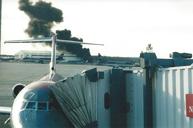
Air Midwest Flight 5481 crash site
from CLT terminal
A quality assurance inspector was wearing two hats the day before this mishap, he was instructing a mechanic new to the airplane's rigging procedure and inspecting that same mechanics work. The only functional check of the work would occur the next day with the airplane filled with passengers. The inspector assured the mechanic in training several steps of the process could be skipped and the elevator was left with inadequate nose down pitch authority.
The report doesn't go into why the nose down authority was compromised other than to compare the end state of two turnbuckles, devices used to adjust the tension of the elevator cables. The mechanic apparently adjusted the nose up turnbuckle much tighter than the nose down turnbuckle. Since the cables wrap around pulleys and are connected indirectly, adjusting one turnbuckle impacts the tension on both. Several of the steps they skipped could have impacted the apparent tension, could. But two of the skipped tests prevented them from detecting their error. They could have determined the precise amount of available elevator travel had they measured flight data recorder pitch data and had they checked actual elevator travel using a "travel board" from its level. But they didn't. The quality assurance instructor didn't think any of that was necessary.
The airplane was also loaded with a CG that was too far aft.
Either one of these problems might have been recoverable, but combined they resulted in killing everyone on board.
I call these mishaps cases of maintenance malpractice because of the short cuts taken, the lack of adequate training and oversight, and the possible impact of fatigue. Whatever the cause, the aircraft was rendered unflyable because of it.

1
Accident report
- Date: 8 January 2003
- Time: 8:49
- Type: Beechcraft 1900D
- Operator: Air Midwest (operating for US Airways Express)
- Registration: N233YV
- Fatalities: 2 of 2 crew, 19 of 19 passengers
- Aircraft Fate: Destroyed
- Phase: Takeoff
- Airport: (Departure) Charlotte-Douglas International Airport, NC (CLT/KCLT), United States of America,
- Airport: (Destination) Greenville-Spartenburg Airport, SC (GSP/KGSP), United States of America
2
Narrative
The Flight
- The dispatch release for flight 5481 showed that a maximum of 32 bags was allowed on the flight. One of the two ramp agents working flight 5481 stated, in a post accident interview, that 23 bags had been checked and that 8 bags were carried on the airplane. The ramp agent stated that two of the checked bags were heavy, with an estimated weight of between 70 and 80 pounds. The ramp agent also stated that he told the captain that some of the bags were heavy, although they were not marked as such. According to the ramp agent, the captain indicated that the bags were fine because a child would be on board, which would allow for the extra baggage weight. The ramp agent estimated that the forward cargo compartment was about 98 percent full by volume.
- Cockpit voice recorder (CVR) information early in the recording indicated that the flight crew was completing the preflight paperwork regarding the airplane's weight and balance. Air Midwest records indicated that flight 5481 departed the gate on time about 0830. The captain was the flying pilot, and the first officer was the non-flying pilot.
- Flight data recorder (FDR) data indicated that, beginning about 0835:16, the flight crew performed a control check of the elevators. The pitch control position parameter, which measures the position of the control column, recorded values from 15° ANU [Airplane Nose Up] to 16.5° AND [Airplane Nose Down]. These values corresponded to elevator positions from full ANU to 7° AND. About 0837:20, the CVR recorded the first officer contacting the CLT Air Traffic Control Tower (ATCT) ground controller and informing him that flight 5481 was ready to taxi. The ground controller instructed the flight crew to taxi to runway 18R.
Source: NTSB AAR-04/01, ¶1.1
A normal flight control check results in elevator positions from 20° to 21° ANU to 14° to 15° AND, so they had less than full available nose down travel.
- About 0846:18, the tower (local) controller cleared flight 5481 for takeoff and instructed the flight crew to turn right to a heading of 230° after takeoff. About 0846:35, the captain asked the first officer to set the takeoff power, and the first officer stated that the power had been set.
- About 0846:48, the airplane's airspeed was above 102 knots, and the elevator position was 7° AND. About 3 seconds later, the elevator position was 1° AND, and the pitch attitude of the airplane began to increase. After 0846:53, the pitch trim started moving AND, and, about 3 seconds later, the captain called for the landing gear to be retracted. About 0846:57, the elevator position returned to 7° AND, and, about 2 seconds later, the CVR recorded the sound of the landing gear retracting.
- About 0847:02, the first officer stated, "wuh," and the captain stated, "oh." About 0847:03, the captain stated, "help me." At that point, the airplane was about 90 feet above ground level, and FDR data showed that the airplane's pitch attitude was 20° ANU and airspeed was 139 knots. About 0847:04, the CVR recorded the captain asking, "you got it?" and FDR data indicated that the flight crew was forcefully commanding AND. During the next 8 seconds, the CVR recorded multiple statements and sounds from both flight crewmembers associated with their efforts to push the airplane's nose down. Also, about 0847:09, the CVR recorded a change in engine/propeller noise and, about 1 second later, the beginning of a sound similar to the stall warning horn.
- About 0847:13, the FDR recorded a maximum pitch attitude of 54° ANU. About 0847:16, the captain radioed the ATCT and stated, "we have an emergency for Air [Midwest] fifty four eighty one," and the CVR recorded the end of the sound similar to the stall warning horn. About 0847:18, the airplane's pitch attitude decreased through 0°, and the elevator position began to move ANU. By 0847:19, the airplane was about 1,150 feet above ground level, and the FDR recorded a maximum left roll of 127° and a minimum airspeed of 31 knots. About 1 second later, the FDR recorded a pitch attitude of 42° AND.
- About 0847:21, the captain stated, "pull the power back," the elevator position reached full ANU, and the airplane's pitch attitude was 39° AND. At 0847:21.7, the CVR recorded the beginning of a sound similar to the stall warning horn, which continued to the end of the recording. About 0847:22, the airplane's roll attitude stabilized at about 20° left wing down; the pitch attitude began to increase; and the elevator position moved in the AND direction, reaching about 8° ANU. About 1 second later, the elevator position began moving in the ANU direction. About 0847:24 the airplane rolled right through wings level, and the pitch attitude increased to about 5° AND.
- About 0847:26, the FDR recorded a maximum right roll of 68° and a maximum vertical acceleration of 1.9 Gs. About the same time, the captain stated, "oh my god ahh," and the first officer stated something similar to, "uh uh god ahh [expletive]." The CVR recording ended at 0847:28.1. The FDR's last recorded pitch attitude was 47° AND; roll attitude was 66° to the right; and pitch control position was 19.2° ANU, which corresponded to an elevator position of full ANU.
- The airplane struck a US Airways maintenance hangar on CLT property and came to rest about 1,650 feet east of the runway 18R centerline and about 7,600 feet beyond the runway 18R threshold. ATCT controllers heard an emergency locator transmitter signal beginning about 0847:29. The accident occurred at 35° 12' 25" north latitude and 80° 56' 46.85" west longitude during daylight hours.
Source: NTSB AAR-04/01, ¶1.1
Maintenance Events Prior to the Flight
- Between the night of January 6 and the morning of January 7, 2003, the accident airplane underwent a detail six (D6) maintenance check at Air Midwest's HTS [Tri-State/Milton J. Ferguson Field, Huntington, WV] maintenance station. Air Midwest contracted with Raytheon Aerospace, LLC (RALLC), to provide mechanics, quality assurance inspectors, and a site manager for the HTS maintenance station. RALLC contracted with Structural Modification and Repair Technicians, Inc. (SMART), to supply the mechanic workforce.
- The RALLC quality assurance inspector on duty the night of January 6th was providing on-the-job training (OJT) to two SMART mechanics on specific tasks associated with the D6 maintenance check. Neither mechanic had previously performed the complete D6 check.
- One of the mechanics receiving OJT was assigned to inspect and check the elevator control cable tension. The D6 inspection procedures checklist (also known as the D6 work card), dated August 25, 2000, indicated that the cable tension was to be checked according to the procedures in chapter 27 of the Raytheon Aircraft Beech 1900D Airliner Maintenance Manual (AMM). The first step on the D6 work card indicated that a temperature reading needed to be taken (to determine the tension values at which the control cables should be set) but did not specify how to take the temperature. The work card showed that the mechanic recorded the temperature as 55° Fahrenheit (F).
- The mechanic stated that he worked under the supervision of the quality assurance inspector to adjust the cables to the proper tension range. According to the D6 work card, the mechanic adjusted the ANU cable tension to 57 pounds and the AND cable tension to 62 pounds.
- The aircraft maintenance record of non-routine items for January 6, 2003, indicated, in a discrepancy block, that the airplane's elevator cable tension was low. A required inspection item (RII) stamp appeared in this block. The form also indicated, in a nature of action block, that the elevator cable tension was adjusted per section 27-30-02 and that the operations check was normal.
- In addition, the mechanic stated that, while adjusting the cable tension, he bypassed several steps of the complete elevator control system rigging procedure (section 27-30-02). The Beech 1900D AMM did not contain a stand-alone procedure for checking elevator cable tension, as called for on the D6 work card, or for adjusting elevator cable tension without rigging the entire elevator control system. The quality assurance inspector stated, during a post accident interview, that he and the mechanic discussed which steps to bypass and that he allowed the mechanic to adjust only the cable tension.
Source: NTSB AAR-04/01, ¶1.1
3
Analysis
Personnel
- The captain, age 25, was hired by Air Midwest in March 2000. She held an airline transport pilot certificate and a Federal Aviation Administration (FAA) first-class medical certificate dated November 19, 2002, with no limitations. The captain received a type rating on the Beech 1900D in March 2001. [ . . . ] The captain received her private pilot certificate in February 1997.
- In post accident interviews, Air Midwest pilots who had flown with the captain made favorable comments about her piloting skills. A check airman stated that the captain had no difficulties during upgrade training and that she demonstrated very good knowledge of the airplane's systems and very good judgment. Another check airman described the captain as one of the better company pilots and stated that she made very good decisions about flying. First officers stated that the captain was a thorough and methodical pilot who controlled the airplane well and involved them with the flight by asking for opinions and letting them review paperwork.
Source: NTSB AAR-04/01, ¶1.5
The captain went from private pilot to airline pilot in just five years and had been flying for just six years on the date of this crash. All indications were that she was a very good pilot and that she showed up for flight well rested.
- In post accident interviews, Air Midwest pilots who had flown with the first officer made favorable comments about his piloting skills. Pilots described the first officer as a talented and very precise pilot with good attention to detail and good communication skills. Pilots also stated that the first officer possessed good situational awareness and good knowledge of the Beech 1900D.
- The quality assurance inspector, age 50, was hired by RALLC in July 2002. He was initially hired as a mechanic at the HTS maintenance station and was subsequently promoted to foreman and secondary (backup) quality assurance inspector. [ . . . ] The primary quality assurance inspector was not at work on the night of January 6, 2003, so the foreman/secondary quality assurance inspector assumed his duties.
- The quality assurance inspector stated that he was providing OJT to two mechanics and that it was his first time training two mechanics while performing inspector duties.
- At the public hearing for this accident, the quality assurance inspector testified that he had performed elevator control system rigging work once.
Source: NTSB AAR-04/01, ¶1.5
The Pitch Control System
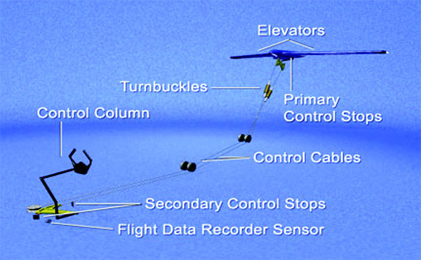
Beech 1900D pitch control system, from NTSB AAR-04/01, figure 4.
- The Beech 1900D airplane is equipped with a mechanically operated pitch control system. The three primary elements of the pitch control system are the elevators, the control column, and the connecting rods and cables. The elevators (left and right) are attached to the trailing edge of the horizontal stabilizer, which is mounted on top of the vertical stabilizer in a T-tail configuration. A pilot pushes forward on the control column to move the elevator trailing edges down (resulting in the airplane pitching AND) and pulls back on the control column to move the elevator trailing edges up (resulting in the airplane pitching ANU).
- The inboard end of each elevator has a control horn that is connected to the elevator surface by a shaft. Four primary stop bolts (left upper, left lower, right upper, and right lower) are mounted on airplane structure. The limit of travel for each of the elevator control horns is contact with an up stop bolt or a down stop bolt. The Beech 1900D AMM, section 27-30-02, indicates that the elevator primary stop deflection settings are 20° +1j/-0° up from the neutral position and 14° +1°/-0° down from the neutral position. The elevator's neutral position is the point at which the position of the trailing edge of the elevator is aligned with the chord plane of the horizontal stabilizer.
- Control cable assemblies (one ANU and one AND) connect the aft bellcrank to the forward bellcrank. The control cable assemblies have two cable sections joined by turnbuckle assemblies located in the base of the vertical stabilizer. Each control cable assembly comprises seven spirally wound strands and has one long and one short component. The turnbuckle assemblies establish the correct tension in the cables. Each turnbuckle assembly consists of a barrel and two threaded cable terminals.
- The accident airplane was equipped with a mechanically operated pitch trim control system. The pitch trim control system includes a single movable trim tab for each elevator and a cable-driven jackscrew actuator for each tab. The trim tabs, which are located on the inboard trailing edge of each elevator, relieve the force a pilot must hold on the control wheel to provide longitudinal control (for example, angle of attack or pitch) of the airplane. According to the Beech 1900D AMM, the trim tabs move from 5.75° ±0.25° up to 17° ±0.5° down. Movement of the trim tabs in the downward direction creates an upward aerodynamic moment on the elevator and results in an ANU pitching moment.
Source: NTSB AAR-04/01, ¶1.6
The procedure that follows includes several steps that are not applicable and some that were intentionally skipped.
Green on black items are not applicable to this airplane.
Black on amber items were applicable but intentionally skipped.
It was possible to view a required rig pin without removing the first officer's seat but it was easier with the seat removed.
- Disconnect the autopilot servo cables.
- Locate and remove all access panels from the vertical and horizontal stabilizers to gain access to the aft elevator bellcrank and the elevator cables.
- Locate and remove the flight compartment seats, carpet, and floorboards to gain access to the forward elevator bellcrank.
- Locate and remove the passenger seats, carpet, and floorboards on the right side of the passenger compartment to gain access to the elevator cable turnbuckles.
- Install an elevator travel board on each elevator at station 50.00.
Source: NTSB AAR-04/01, ¶1.6.3.1] ELEVATOR CONTROL SYSTEM RIGGING
A travel board is a calibrated template that attaches to the trailing edge of the horizontal stabilizer that allows a person positioned at eye level to see exactly how far up or down the elevator has moved. The text of the report's factual information does not note this step was skipped but the analysis and findings section imply that it was. It makes sense that it was, otherwise the mechanics would have detected the resulting limited elevator travel.
- Adjust the center-to-center length of the push-pull tube assembly between the control column and the forward elevator bellcrank to a dimension of 15.12 ± 0.06 inch.
- Adjust the surface stop bolts on the elevator control horn support for up-travel of 20° + 1° - 0 and down-travel of 14° + 1° - 0°.
- Verify the bob weight stop bolt clearance is 0.5 ± 0.06 inch. Adjust if necessary.
- Adjust the forward bellcrank stops for 0.37 ± 0.06 inch clearance from the stop bolts.
- Verify the forward bellcrank stop bolts make contact before the bob weight stop bolts make contact with the weight.
- Install a rig pin in the aft elevator bellcrank.
- Adjust the pushrods between the aft elevator bellcrank and the elevator to position the elevator at neutral (0° deflection).
- Remove the rig pin from the aft elevator bellcrank.
- Remove the safety clips from the turnbuckles and release cable tension.
- Move the control yoke to install the rig pin in the forward elevator bellcrank.
- Tighten the elevator-up cable until the elevator rises to neutral (0° on the travel board).
- Tighten the elevator-down cable until the average tension of the up- and down-cables is 66 ± 8 pounds (the sum of up-cable and down-cable tensions, divided by two). Refer to Figure 203.
- Continue to balance the adjustment of the two cables until the average tension is 66 ± 8 pounds while maintaining 0° deflection of the elevator.
- Perform the CONTROL COLUMN SUPPORT ROLLER INSPECTION procedure.
- Install safety clips on the turnbuckles.
- On aircraft equipped with the F1000 Flight Data Recorder, calibrate the Pitch Position Potentiometer. Perform the FLIGHT DATA RECORDER (FDR)̃ PITCH ADJUSTMENT procedure.
NOTE: Verify threads are visible through the inspection holes at the end of the pushrods after adjustments are made.
Source: NTSB AAR-04/01, ¶1.6.3.1] ELEVATOR CONTROL SYSTEM RIGGING
The mechanic thought this unnecessary and the quality assurance inspector thought the airplane didn't have an FDR.
- Remove the travel boards from the horizontal stabilizers.
Source: NTSB AAR-04/01, ¶1.6.3.1] ELEVATOR CONTROL SYSTEM RIGGING
See step e.
- Connect the autopilot servo cables to the elevator primary control cables.
- Install the seats, carpet and floorboards.
- Replace all access panels.
Source: NTSB AAR-04/01, ¶1.6.3.1] ELEVATOR CONTROL SYSTEM RIGGING
Step a, to disconnect the autopilot servo cables, and step w, to connect the autopilot servo cables to the elevator primary control cables, were not applicable to the accident airplane because it did not have an autopilot. Step d, to locate and remove the passenger seats, carpet, and floorboards on the right side of the passenger compartment to gain access to the turnbuckles, was not applicable because the elevator cable turnbuckles for the Beech 1900D model are not located under the passenger compartment floorboards.
- The mechanic indicated that he bypassed step c, to locate and remove the flight compartment seats, carpet, and floorboards to gain access to the forward elevator bellcrank, because the quality assurance inspector told him that the flight compartment seats and floorboards did not need to be removed to comply with the rigging procedure. In fact, the mechanic stated that access to the rig pin hole was adequate without removing the seats and the floorboards because the foreman showed the mechanic a small access panel that needed to be opened to access the forward bellcrank rig pin hole. The mechanic also stated that he bypassed step f, to adjust the center-to-center length of the forward push-pull tube to a dimension of 15.12 inches ±0.06 inch, with the quality assurance inspector's concurrence.
- The mechanic indicated that he bypassed step g, to adjust the stop bolts on the elevator control horn supports for a deflection setting of 20° +1°/-0° up and 14° +1°/-0° down, because he did not think that cable tensioning required a measurement of the deflection settings. The mechanic stated that he had manually pushed the elevators up and down before rigging to determine if the elevator control horns were hitting the stops.
- The mechanic stated that he decided, and the quality assurance inspector concurred, that the following steps were not required: step h, to verify the bob weight stop bolt clearance and adjust if necessary; step i, to adjust the forward bellcrank stops for clearance from the stop bolts; and step j, to verify that the forward bellcrank stop bolts make contact before the bob weight stop bolt makes contact with the weight. The mechanic stated that he bypassed part of step n, to release cable tension, because he could adjust cable tension by tightening the cables without releasing them before the adjustment.
- The mechanic stated that he bypassed step s, to perform the control column support roller inspection procedure, because he decided that it was not required. The quality assurance inspector concurred. The mechanic also stated that he bypassed step u, to calibrate the F1000 FDR pitch position potentiometer and to perform the FDR pitch adjustment procedure, because he did not think that the calibration needed to be done. The quality assurance inspector stated that he did not think that an FDR was installed on the airplane.
Source: NTSB AAR-04/01, ¶1.6.3.2
Of course there was indeed an FDR installed.
- During a post accident interview, the mechanic and quality assurance inspector further stated that steps c, f, g, h, i, j, n, and s were not required because those steps were only necessary for cable replacement and not for cable tensioning. The Air Midwest regional site manager stated, during a post accident interview, that all of these steps should have been followed, except for step n (releasing the cable tension before a readjustment of the cables). The regional site manager thought that loosening the cables would not have affected the final outcome of a proper rig.
- In addition, the mechanic stated that he bypassed the Elevator Control System Friction Test described in section 27-30-02 of the Beech 1900D AMM because he decided that the test was not required. The quality assurance inspector concurred.
Source: NTSB AAR-04/01, ¶1.6.3.2
- The rivets connecting the elevator control horns to the elevator shafts were tight, and the control horns were solidly fixed to the elevator shafts. The control horns moved freely in their respective bearings. The primary stop bolts were attached to the elevator control horn supports and were found safety wired.
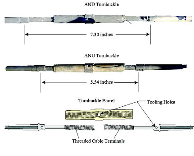
- The ANU turnbuckle was almost fully contracted, and the AND turnbuckle was almost fully extended. The measurement from the center of the tooling hole in one threaded cable terminal to the center of the tooling hole in the other cable terminal was 5.54 inches for the ANU turnbuckle and 7.30 inches for the AND turnbuckle. In addition, the AND turnbuckle had one thread visible, and the ANU turnbuckle did not have any threads visible. Figure 6 shows the turnbuckles as found in the wreckage and a drawing that shows a turnbuckle barrel and threaded cable terminals.
- The AND turnbuckle was extended 1.76 inches more than the ANU turnbuckle. After the accident, Air Midwest surveyed its entire fleet of 42 Beech 1900D airplanes, which represented 25 percent of the 164 Beech 1900D airplanes active in the North American fleet. Air Midwest data submitted to the Safety Board indicated that, on average, the AND turnbuckle was extended 0.04 inch less than the ANU turnbuckle.
Source: NTSB AAR-04/01, ¶1.12.4
- The elevator trim tab control wheel was intact and was attached in the cockpit. The pitch trim appeared to be near the full AND position. The pitch trim control cables were broken. The control cables were in the correct orientation. The left and right drums had their respective cables wrapped around to the middle position.
Source: NTSB AAR-04/01, ¶1.12.4
- Flight data recorder (FDR) and CVR data from the accident flight showed that the airplane was rotating airplane nose up (ANU) after takeoff, even though the flight crew was pushing the control column fully forward and trimming the airplane in the airplane-nose-down (AND) direction. Neither of these actions allowed the flight crew to control the airplane's pitch attitude.
- FDR data, ground test results, and the airplane performance study for this accident showed that, before the accident airplane's detail six (D6) maintenance check on January 6, 2003, at Air Midwest's HTS maintenance station, the airplane's full range of downward elevator travel was available. FDR data, ground test results, and the airplane performance study also showed that, after the D6 maintenance check, the airplane's downward elevator travel was limited to about 7° rather than the 14° to 15° specified in the Beech 1900D Airliner Maintenance Manual (AMM).
- The mechanic determined that the accident airplane's cables needed to be adjusted because their average tension was too low. He stated that he adjusted the cables and performed some, but not all, of the steps of the elevator control system rigging procedure (section 27-30-02) in the Beech 1900D AMM. However, whenever cable tension adjustments are made, the entire elevator control system rigging procedure needs to be performed and not just those steps that apply to cable tensioning.
- Examination of the accident airplane's pitch control cable turnbuckles as found in the wreckage revealed that the AND turnbuckle, which measured 7.30 inches in length, was extended 1.76 inches more than the ANU turnbuckle, which measured 5.54 inches in length. However, according to data from Air Midwest's post accident survey of its entire fleet of 42 Beech 1900D airplanes, the AND turnbuckle was extended, on average, only 0.04 inch less than the ANU turnbuckle. Further, ground tests showed that turnbuckles adjusted to the lengths of those found in the wreckage would result in limited downward elevator travel, although the FDR would indicate that full downward travel was available.
- The Safety Board concludes that the accident airplane entered the D6 maintenance check with an elevator control system that was rigged to achieve full elevator travel in the downward direction. The Safety Board further concludes that the accident airplane's elevator control system was incorrectly rigged during the D6 maintenance check and that the incorrect rigging restricted the airplane's elevator travel to 7° AND, or about one-half of the downward travel specified by the airplane manufacturer.
- The only visible sign of the mis-rig during the first officer's external preflight inspection would have been a change in the elevator resting position. The normal elevator resting position is between 14° and 15° AND; after the mis-rig, the elevator resting position was about 7° AND. Because the horizontal stabilizer on a parked Beech 1900D is located about 15 feet above the ground, it would be difficult to detect the change in the elevator resting position from the ground. [ . . . ] The Safety Board concludes that the changes in the elevator control system resulting from the incorrect rigging were not conspicuous to the flight crew.
- The Safety Board concludes that the RALLC quality assurance inspector did not provide adequate OJT and supervision to the SMART mechanic who examined and incorrectly adjusted the elevator control system on the accident airplane.
- The Beech 1900D elevator control system rigging procedure (section 27-30-02) does not include provisions for adjusting cable tension as an isolated task. However, the mechanic decided to adjust the cables as an isolated task and, as a result, did not follow each step included in the rigging procedure. The quality assurance inspector was aware that the mechanic was selectively performing steps from the rigging procedure and that he was only adjusting cable tension. In fact, the inspector stated, during a post accident interview, that he did not think the manufacturer intended for mechanics to follow the entire rigging procedure and that the entire procedure had not been followed when past cable tension adjustments were made.
- The mechanic skipped nine applicable steps in the Beech 1900D elevator control system rigging procedure (see section 1.6.3.2).130 One of these steps indicated that, for airplanes equipped with an F-1000 FDR, the pitch position potentiometer needed to be calibrated (step u). The mechanic was required to perform this step because the accident airplane had an F-1000 FDR installed. Step u indicated that, to calibrate the pitch position potentiometer, the mechanic needed to perform the FDR pitch adjustment procedure described in another section of the Beech 1900D AMM. This procedure referred the mechanic to a table that specified eight different elevator settings, ranging from 14° AND to 20° ANU (including 0°), and instructed the mechanic to record the FDR readout for these settings. The mechanic, however, would not have been able to move the elevator to the first setting, 14° AND, because elevator travel was restricted to about 7° AND.
- The performance of step u would have likely alerted the mechanic or the quality assurance inspector that the elevator control system was not properly rigged. However, the mechanic indicated that he skipped step u because he thought the calibration did not need to be done. The quality assurance inspector stated that he did not think that an FDR was installed on the airplane, but the inspector should have known that the airplane was equipped with an FDR because most, if not all, Beech 1900D airplanes were outfitted with an FDR. Also, the inspector could have easily determined that the airplane was equipped with an FDR. Specifically, the wiring and the sensor for the FDR were in the same area of the airplane where maintenance was being performed. Also, the FDR unit is mounted in the forward (AFT1) cargo compartment and is readily visible. In addition, a circuit breaker for the FDR is located in the cockpit.
- The post maintenance checks performed by the quality assurance inspector and the mechanic were not adequate to detect the elevator control system mis-rig [ . . . ] A functional check at the end of the procedure would have provided a more comprehensive, systematic, and direct method to ensure that any mis-rigging problem was caught before an airplane was returned to service. Such a functional check would consist of a mechanic in the cockpit pushing the control wheel full forward and then pulling the wheel full aft while another mechanic, who was at eye level with the horizontal stabilizer, measured the position of the elevator using a travel board. This process would determine whether the elevator achieved the correct deflection for the full forward and full aft movement of the control column.
Source: NTSB AAR-04/01, ¶2.3
- The airplane performance study for flight 5481 determined that the accident airplane's actual weight was about 17,700 pounds and that its actual CG position was about 45.5 percent MAC. As a result, flight 5481 had exceeded the Beech 1900D certified weight limit of 17,120 pounds and the certified aft CG limit of 40 percent MAC.
- The restricted elevator travel alone and the aft CG alone would not have been sufficient to cause the uncontrolled pitch up that led to the flight 5481 accident. The Safety Board concludes that flight 5481 had an excessive aft CG, which, combined with the reduced downward elevator travel resulting from the incorrect elevator rigging, rendered the airplane uncontrollable in the pitch axis.
Source: NTSB AAR-04/01, ¶2.4
Findings
- The accident airplane entered the detail six maintenance check with an elevator control system that was rigged to achieve full elevator travel in the downward direction.
- The accident airplane's elevator control system was incorrectly rigged during the detail six maintenance check, and the incorrect rigging restricted the airplane's elevator travel to 7° airplane nose down, or about one-half of the downward travel specified by the airplane manufacturer.
- The changes in the elevator control system resulting from the incorrect rigging were not conspicuous to the flight crew.
- The Raytheon Aerospace quality assurance inspector did not provide adequate on-the-job training and supervision to the Structural Modifications and Repair Technicians mechanic who examined and incorrectly adjusted the elevator control system on the accident airplane.
- Because the Raytheon Aerospace quality assurance inspector and the Structural Modifications and Repair Technicians mechanic did not diligently follow the elevator control system rigging procedure as written, they missed a critical step that would have likely detected the mis-rig and thus prevented the accident.
- A complete functional check at the end of maintenance for critical flight systems or their components would help to ensure their safe operation, but no such check is currently required.
- Flight 5481 had an excessive aft center of gravity, which, combined with the reduced downward elevator travel resulting from the incorrect elevator rigging, rendered the airplane uncontrollable in the pitch axis.
- When an inspector provides on-the-job training for a required inspection item (RII) maintenance task and then inspects that same task, the independent nature of the RII inspection is compromised.
Source: NTSB AAR-04/01, ¶3.1
4
Cause
- The National Transportation Safety Board determines that the probable cause of this accident was the airplane's loss of pitch control during takeoff. The loss of pitch control resulted from the incorrect rigging of the elevator control system compounded by the airplane's aft center of gravity, which was substantially aft of the certified aft limit.
- Contributing to the cause of the accident were (1) Air Midwest's lack of oversight of the work being performed at the Huntington, West Virginia, maintenance station; (2) Air Midwest's maintenance procedures and documentation; (3) Air Midwest's weight and balance program at the time of the accident; (4) the Raytheon Aerospace quality assurance inspector's failure to detect the incorrect rigging of the elevator control system; (5) the Federal Aviation Administration's (FAA) average weight assumptions in its weight and balance program guidance at the time of the accident; and (6) the FAA's lack of oversight of Air Midwest's maintenance program and its weight and balance program.
Source: NTSB AAR-04/01, ¶3.1
References
(Source material)
NTSB Aircraft Accident Report, AAR-04/01, Loss of Pitch Control During Takeoff, Air Midwest Flight 5481, Raytheon (Beechcraft) 1900D, N233YV, Charlotte, North Carolina, January 8, 2003