If you can fly an ILS without the glide slope, you can fly a back course localizer. Because you are closer to the localizer antenna, the course information is more narrow and can seem "sensitive." Just don't forget the switch that allows the flight director to get its mind right about the front course versus the back course. Also remember that most aircraft will not allow you to fly the FMS, "blue needles" in the G450, with a localizer tuned.
— James Albright

Updated:
2012-04-11
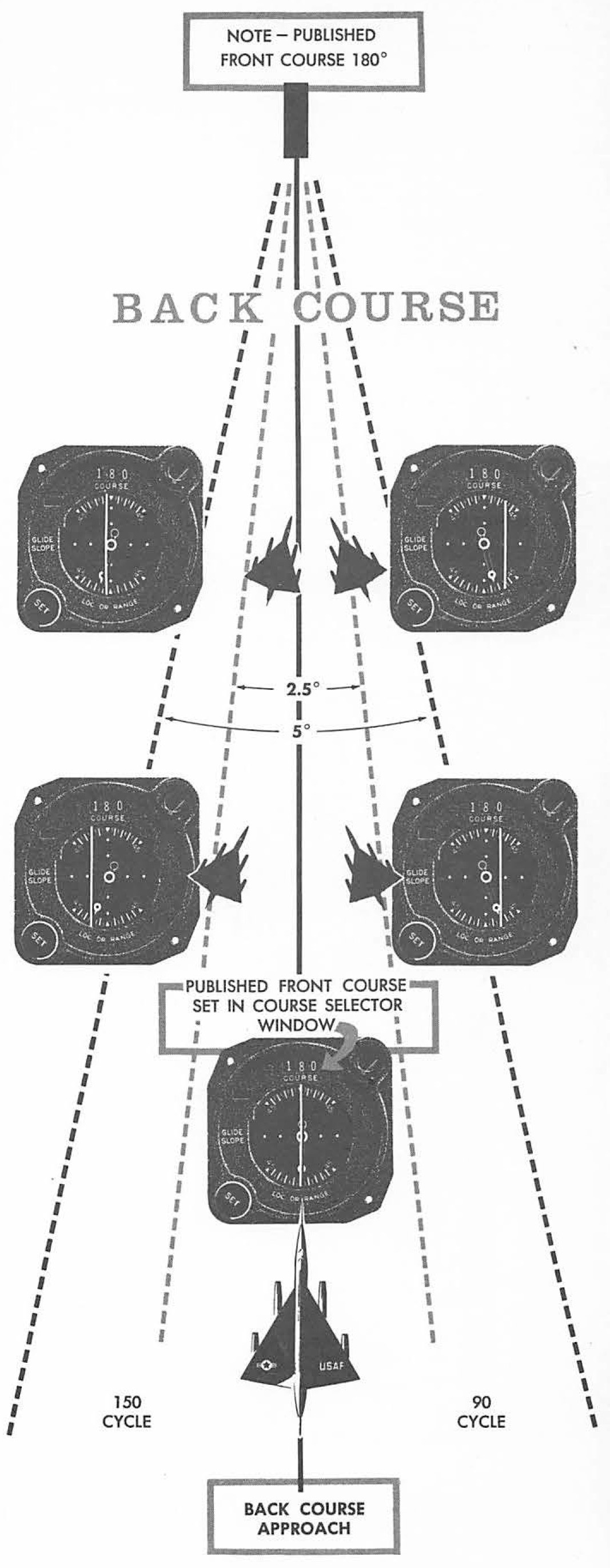
Back course localizer, AFM 51-37 (1966), Figure 16-5
The figure with the B-58 Hustler flying a back course? That is from my very first instrument flying manual, Air Force Flight Manual 51-37, figure 16-5.

1
General description
- The back course localizer approach provides the lateral guidance of an ILS approach without the glide slope information.
- Instrument landing system (ILS): An electronic system that provides both horizontal and vertical guidance to a specific runway, used to execute a precision instrument approach procedure. The ILS system provides both course and altitude guidance to a specific runway. The ILS system is used to execute a precision instrument approach procedure or precision approach. The system consists of the following components:
- A localizer provides horizontal (left/right) guidance along the extended centerline of the runway.
- A glide slope provides vertical (up/down) guidance toward the runway touchdown point, usually at a 3° slope.
- Marker beacons provide range information along the approach path.
- Approach lights assist in the transition from instrument to visual flight.
Source: Instrument Flying Handbook, pg. 7-27

Localizer Coverage Limits, from Instrument Flying Handbook, Figure 7-24.
Equipment Requirements
Localizer
- The localizer (LOC) ground antenna array is located on the extended centerline of the instrument runway of an airport, remote enough from the opposite (approach) end of the runway to prevent it from being a collision hazard. This unit radiates a field pattern, which develops a course down the centerline of the runway toward the middle markers (MMs) and outer markers (OMs), and a similar course along the runway centerline in the opposite direction. These are called the front and back courses, respectively. The localizer provides course guidance, transmitted at 108.1 to 111.95 MHz (odd tenths only), throughout the descent path to the runway threshold from a distance of 18 NM from the antenna to an altitude of 4,500 feet above the elevation of the antenna site.
- The localizer course is very narrow, normally 5°. This results in high needle sensitivity. With this course width, a full-scale deflection shows when the aircraft is 2.5° to either side of the centerline. This sensitivity permits accurate orientation to the landing runway. With no more than one-quarter scale deflection maintained, the aircraft will be aligned with the runway.
Source: Instrument Flying Handbook, pg. 7-27
Marker Beacons.
- Two VHF marker beacons, outer and middle, are normally used in the ILS system. A third beacon, the inner, is used where Category II operations are certified. A marker beacon may also be installed to indicate the FAF on the ILS back course.
- The OM is located on the localizer front course 4 to 7 miles from the airport to indicate a position at which an aircraft, at the appropriate altitude on the localizer course, will intercept the glide path. The MM is located approximately 3,500 feet from the landing threshold on the centerline of the localizer front course at a position where the glide-slope centerline is about 200 feet above the touchdown zone elevation. The inner marker (IM), where installed, is located on the front course between the MM and the landing threshold. It indicates the point at which an aircraft is at the decision height on the glide path during a Category II ILS approach. The back-course marker, where installed, indicates the back-course FAF.
Source: Instrument Flying Handbook, pg. 7-27
Compass Locator.
Compass locators are low-powered NDBs and are received and indicated by the ADF receiver. When used in conjunction with an ILS front course, the compass locator facilities are collocated with the outer and/or MM facilities. The coding identification of the outer locator consists of the first two letters of the three-letter identifier of the associated LOC. For example, the outer locator at Dallas/Love Field (DAL) is identified as “DA.” The middle locator at DAL is identified by the last two letters “AL.”
Source: Instrument Flying Handbook, pg. 7-27
Approach Lighting Systems (ALS)
Normal approach and letdown on the ILS is divided into two distinct stages: the instrument approach stage using only radio guidance, and the visual stage, when visual contact with the ground runway environment is necessary for accuracy and safety. The most critical period of an instrument approach, particularly during low ceiling/visibility conditions, is the point at which the pilot must decide whether to land or execute a missed approach. As the runway threshold is approached, the visual glide path will separate into individual lights. At this point, the approach should be continued by reference to the runway touchdown zone markers. The ALS provides lights that will penetrate the atmosphere far enough from touchdown to give directional, distance, and glide path information for safe visual transition.
Source: Instrument Flying Handbook, pg. 7-27
More about that: Approach Lighting System.
2
Regulatory requirements
Pilots must be instrument rated and the aircraft be equipped with the appropriate airborne equipment to execute back course localizer approaches.
Source: Instrument Flying Handbook, pg. 7-27
3
Advantages
The Localizer Back Course provides an accurate centerline.
4
Disadvantages
The Localizer Back Course provides several opportunities to make mistakes setting the back course instead of the front course or forgetting to press the flight director's BC button, for example.
It also tempts one to "dive and drive." You can, and should, fly a Continuous Descent Final Approach for most Localizer Back Course approaches.
Your altimeter is critical on these types of non-precision approaches and having the wrong QNH set can easily lead to a Controlled Flight Into Terrain (CFIT), as many accidents over the years prove. It is a good technique to verify the correct QNH with tower once you are handed over. Another common mistake is to think of your radio altitude (AGL) when targeting your MDA which should be a barometric altitude (MSL). Asking for the QNH will serve as a reminder where your focus needs to be.
5
Limitations
The ILS and its components are subject to certain errors, which are listed below. Localizer and glide-slope signals are subject to the same type of bounce from hard objects as space waves.
- Reflection. Surface vehicles and even other aircraft flying below 5,000 feet above ground level (AGL) may disturb the signal for aircraft on the approach.
- False courses. In addition to the desired course, glideslope facilities inherently produce additional courses at higher vertical angles. The angle of the lowest of these false courses will occur at approximately 9°–12°. An aircraft flying the LOC/glide-slope course at a constant altitude would observe gyrations of both the glide-slope needle and glide-slope warning flag as the aircraft passed through the various false courses. Getting established on one of these false courses will result in either confusion (reversed glide-slope needle indications), or result in the need for a very high descent rate. However, if the approach is conducted at the altitudes specified on the appropriate approach chart, these false courses will not be encountered.
Source: Instrument Flying Handbook, pg. 7-27
References
(Source material)
Air Force Manual (AFM) 51-37, Instrument Flying, 20 January 1966
Air Force Manual (AFM) 51-37, Instrument Flying, 1 December 1976
FAA-H-8083-15, Instrument Flying Handbook, U.S. Department of Transportation, Flight Standards Service, 2001.