The aircraft's left engine tore away during takeoff, taking enough of the wing structure to cause the left side leading edge slats to retract and cause an asymmetric stall. The pilots flew the air carrier's mandated procedure to pitch up to V2 and that caused the airplane to depart controlled flight. But none of that is what really caused the mishap.
— James Albright

Updated:
2016-07-08
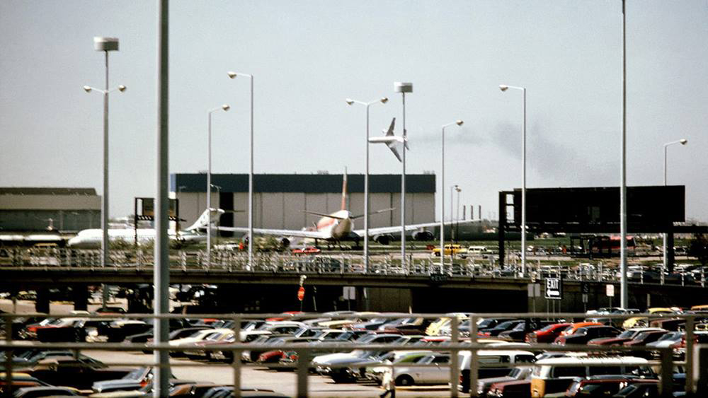
Flight 191,
from Chicago Tribune.
This is a mishap caused by bureaucracy at several levels:
- The aircraft designers and FAA certification review failed to consider the vulnerability of the pylon structure to damage during maintenance.
- American Airlines maintenance and engineering personnel evaluated and implemented a procedure for removing and replacing the wing engines and pylons as a single unit, rather than the two step procedure (engine and pylon separately), despite the manufacturer's warning of unacceptable risk. While one airline was able to accomplish this streamlined procedure without damage to components using a hoist, two other airlines (including American) used a forklift which resulted in damage to a parts of the pylon assembly.
- American Airlines maintenance personnel did not inform engineering or quality control agencies about the difficulties of removing and replacing the engine and pylon combination using a forklift.
- The pilots flying "by the book" provided them could not have recovered. They were in complete control when the airplane had excess speed, but their procedures required them to pitch up to capture V2. As the speed fell below V2+6, the left wing began to stall and the aircraft started to roll to the left. Simulator tests showed that at V2 + 10 the crash may not have occurred.
So what can we, as operators, learn from this?
- We do not always have the expertise and resources to reinvent manufacturer procedures. McDonnell-Douglas was sure to have looked at the engine and pylon parts following their recommended procedures. The American Airlines maintenance and engineering teams were unlikely to have applied as much analysis into their revised procedures. We should be very reluctant to reinvent the wheel when it comes to these procedures.
- Just because your company hands down procedures to you doesn't mean they necessarily have thought of everything. If you are the person turning the wrench you are duty bound to speak up when something doesn't seem right.
- We pilots accumulate flying lessons from a broad range of sources, including other aircraft types. At the time of this crash the United States Air Force was flying the DC-10 using engine failure during takeoff procedures more commonly found in Boeing aircraft. Specifically, the USAF procedure at the time was to keep the speed at the time of engine failure up to V2 + 10. Had this crew been using these procedures, they probably would have survived. But that isn't to say these pilots were in anyway to blame; they were following American Airlines procedures.

1
Accident report
- Date: 25 MAY 1979
- Time: 15:04
- Type: McDonnell Douglas DC-10-10
- Operator: American Airlines
- Registration: N110AA
- Fatalities: 13 of 13 crew, 258 of 258 passengers, 2 ground
- Aircraft Fate: Destroyed
- Phase: Takeoff
- Airport: (Departure) Chicago-O'Hare International Airport, IL (ORD/KORD), United States of America
- Airport: (Destination) Los Angeles International Airport (LAX/KLX), United States of America
2
Narrative
Correlation of the DFDR [Digital Flight Data Recorder] and CVR [Cockpit Voice Recorder] recordings disclosed that the flightcrew had set the flaps and stabilizer trim at 10° and about 5° aircraft nose up, respectively, for takeoff. A rolling takeoff was made, takeoff thrust was stabilized at [?] KIAS, and left rudder and right aileron were used to compensate for the right crosswind. The V1 and VR callouts were made about 2 sec after these speeds were recorded by the DFDR. The elevator began to deflect up at VR. The aircraft began to rotate upward immediately and continued upward at a rate of 1.5° per sec. Flight 191 accelerated through V2 speed during rotation and before it lifted off the runway. The last stable takeoff thrust on the No. 1 engine was recorded 2 sec before liftoff. One second later, the word "damn" was recorded on the CVR, and then the CVR ceased operating.
Source: NTSB Report, ¶1.11
Flight 191 became airborne about 6,000 ft from the start of the takeoff roll and remained airborne for 31 sec. It lifted off at V2 + 6 KIAS and at 10° pitch attitude. Two seconds after liftoff, the DFDR reading for the No. 1 engine's N1 was zero, the No. 2 engine's N2 speed was increasing through 101 percent, and the No. 3 engine's N1 was essentially at the takeoff setting.
Source: NTSB Report, ¶1.11
Witnesses saw white smoke or vapor coming from the vicinity of the No. 1, engine pylon. During rotation the entire No. 1 engine and pylon separated from the aircraft, went over the top of the wing, and fell to the runway.
Source: NTSB Report, ¶1.1
Flight 191 lifted off about 6,000 ft down runway 32R, climbed out in a wings-level attitude, and reached an altitude of about 300 ft above the ground (a.g.1.) with its wings still level. Shortly thereafter, the aircraft began to turn and roll to the left, the nose pitched down, and the aircraft began to descend. As it descended, it continued to roll left until the wings were past the vertical position.
Source: NTSB Report, ¶1.1
Flight 191 crashed in an open field and trailer park about 4,600 ft northwest of the departure end of runway 32R. The aircraft was demolished during the impact, explosion, and ground fire.
Source: NTSB Report, ¶1.1
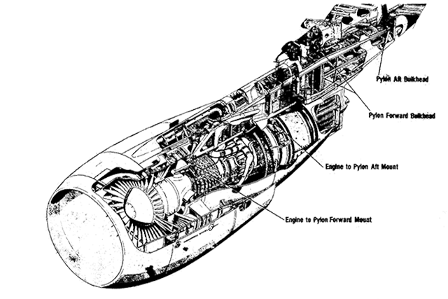
Engine and pylon assembly, from NTSB Report, figure 2.
- The first marks made by engine contact of the No. 1 engine and pylon with the runway began about 19 ft. to the right of the centerline lights and about 6,953 ft beyond the southeast end of runway 32R. Other parts of engine and pylon structure were located in this area; however, no spoiler actuators or hydraulic lines were found.
- The pylon is attached to the wing using spherical ball joints in three different structural elements. Two of the spherical joints are aligned vertically in a forward bulkhead which is attached to structure in the wing forward of the front spar. Another spherical joint behind the forward bulkhead transmits thrust loads from pylon structure into a thrust link which in turn is connected through another spherical joint to structure on the lower surface of the wing. The third attachment point is a spherical joint in the pylon aft bulkhead which attaches to a clevis mounted on the underside of the wing. The pylon forward bulkhead and portions of the flange from the pylon aft bulkhead either remained with the separated No. 1 pylon or were scattered along the runway. (See figures 2 and 3.) The No. 1 pylon's aft clevis attach assembly and portions of the pylon aft bulkhead, wing thrust angle assembly and thrust link, and pylon forward bulkhead attach assembly remained with the wing.
- The pylon forward bulkhead was bent forward about 30° and most of the bolts which held the bulkhead upper plates were missing. The upper 12 inches of the forward plate were bent forward an additional 10° to 15°. The aft plate Was broken below the thrust fitting connection, and a Large piece of the upper left corner was missing.
- The wing's forward support fitting, which attached the pylon forward bulkhead to the wing at the upper and lower plugs and spherical bearings, was found at the main wreckage site. The upper and lower plugs and their attaching hardware were intact, and the upper and lower spherical bearings were attached to the fitting.
- The pylon thrust fitting remained attached to the forward portion of the pylon's aft upper spar web. The pylon thrust link, which attached the pylon thrust fitting to the wing thrust angles, was found at the main wreckage site attached to a portion of the wing thrust angles. Its forward spherical bearing was cocked to the extreme left, and a segment of the bearing which had broken away was found on the runway.
- The thrust bushing bolt had broken in two parts, both of which were found in the grass adjacent to the runway. The bolt nut was attached to one of the broken pieces, and the faces of the nut were gouged severely. Except for one lubrication retainer washer, which was not found, the remaining portions of the thrust bushing bolt assembly were found along the runway. One shim spacer from the assembly was crushed severely while the other was relatively undamaged.
- The upper two-thirds of the pylon aft bulkhead separated from the flanges around its periphery and was found in the wreckage. The top two pieces of its attach lugs had separated from the bulkhead, and the left side of the bulkhead was gouged heavily near the lower edge of the wing clevis lug, which attached the aft bulkhead to the wing. The wing clevis was attached to the wing. The aft bulkhead's spherical bearing was attached to the clevis, and the separated pieces of the aft bulkhead's attach lugs were found on top of the spherical bearing.
- A 3-ft section of the left wing's leading edge, just forward of the point where the forward part of the pylon joined the wing, was torn away when the engine pylon assembly separated from the aircraft. The No. 1 and No. 3 hydraulic system's extension and retraction lines and the follow up cables for the left wing's outboard slat drive actuators were severed. Thirty-five of the 36 leading edge slat tracks were examined. The examination disclosed that at impact the left wing's outboard slats were retracted, while the left wing's inboard slats and the right wing's inboard and outboard slats were extended to the takeoff position.
Source: NTSB Report, ¶1.12
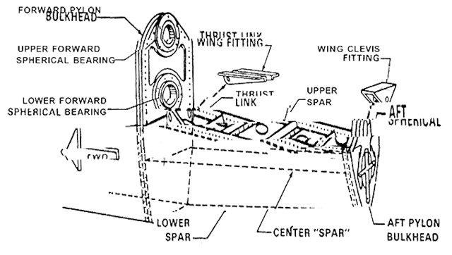
Pylon assembly, from NTSB Report, figure 3.
- N110AA's pylon aft bulkhead was examined at the Safety Board's metallurgical laboratory. The examination disclosed a fracture of the upper forward flange. The larger part of this fracture was just forward of the radius between the flange and forward bulkhead plane and was about 10 inches long in the inboard-outboard direction. The fracture characteristics were typical of an overload separation.
- Fatigue cracking was evident at both ends of the fracture.
- The examination also disclosed that three shims were installed on the upper surface of the forward upper flange.
- Taking into account the stack up of the forward flange created by the spar web, doubler, and fasteners, the clearance between the bottom of the clevis and the top of the web fasteners could be about .005 to 045 inch. The addition of a shim would narrow the clearance, and taking into account all tolerances in the spherical assembly, there could be an interference.
Source: NTSB Report, ¶1.16.2
- The evidence indicated that the maximum interference that would result from the insertion of the .050-inch-thick shim was .024 inch. The static tests conducted by American Airlines and McDonnell-Douglas showed that a crack would begin at a deflection of about 0.1 inch; thus, in the worst case, an additional deflection would be required to crack the flange.
- During ground operation of the aircraft--taxiing, landing, and takeoff rolls--the aft bulkhead is subjected to compression loads and the aft end of the pylon is forced upward. During rotation, the loading changes and the aft bulkhead is subjected to tension-type loads. Those loads were found to be significantly lower than the fail-safe design loads.
Wind Tunnel and Simulator Tests
- The wind tunnel data for the damaged aircraft were correlated with the DFDR data so that the simulator data reflected those derived from Flight 191's DFDR. With the slats extended, the [all]-engine-operating stall speed was 124 KIAS; the asymmetric slat-retracted stall speed for the left wing was 159 KIAS and the estimated wings-level VMC for the damaged aircraft was 128 KIAS With a 4° left bank--a bank into the missing engine--159 KIAS was the minimum speed at which directional control could be maintained with the engines operating at takeoff thrust.
- During the tests, about 70 takeoffs and 2 simulated landings were conducted. In all cases where the pilots duplicated the control inputs and pitch attitudes shown on the Flight 191's DFDR, control of the aircraft was lost and Flight 191's flight profile was duplicated. Those pilots who attempted to track the flight director's pitch command bars also duplicated Flight 191's DFDR profile.
- According to American Airline's procedures, the standard rate of rotation is between 3° to 4° per second, whereas Flight 191 rotated at only about l.5° per second. In those simulations in which the standard rate was used, the aircraft lifted off at a lower airspeed, and the airspeed did not increase to the levels recorded by Flight 191's DFDR. The left roll began at 159 KIAS however. Because of the lesser amount of excess airspeed, the roll started below 100 ft a.g.l. In those cases where slat retraction was delayed, the left roll started at a higher altitude but its characteristics remained the same. In all cases, however, the roll began at 159 KIAS.
- In many cases, the pilots, having recognized the start of the roll at a constant pitch attitude, lowered the nose, increased airspeed, recovered, and continued flight. The roll angles were less than 30°, and about 80 percent right rudder and 70 percent right-wing-down aileron were required for recovery. In those cases where the pilot attempted to regain the 14° pitch attitude commanded by the flight director command bars, the aircraft reentered the left roll.
Source: NTSB Report, ¶1.16.4
Air Carrier Maintenance Procedures
- On May 31, 1975, and February 1, 1978, the McDonnell-Douglas issued DC-10 Service Bulletins 54-48 and 54-59, respectively. Both bulletins were issued to correct service-related unsatisfactory conditions. [ . . .] Compliance was recommended at the "operator's convenience."
- Service Bulletin 54-48 directed that the pylons were to be removed in accordance with the procedures contained in Chapter 54-00-00 of the DC-10 Maintenance Manual. Chapter 54-00-00 called for, first, removal of the engine and then removal of the pylon. The pylon alone weighs about 1,865 lbs. and its c.g. is located about 3 ft forward of the forward attachment points whereas the pylon and engine together weigh about 13,477 lbs. and the c.g. of the assembly is located about 9 ft forward of the forward attachment points. According to the manual, the sequence shown for the removal of the attach fittings was: The forward upper attach assembly, the forward lower attach assembly, the thrust link, and the aft bolt and bushing.
- American Airlines decided to comply with Service Bulletins 54-48 and 54-59 and to perform the work during a maintenance "C" check at its Tulsa maintenance facility. On July 28, 1978, American Airlines issued Engineering Change Order (ECO) R-2693 establishing the maintenance procedures for accomplishing the modifications contained in the service bulletins.
- The ECO was developed from the company's experiences during modifications on four VC-10-30's during the spring and fall of 1977, at Los Angeles, California. American Airlines, in accordance with a contract with a foreign carrier, modified four of the foreign carrier's DC-10-30's. The carrier also requested that American Airlines perform the spherical bearing replacement program contained in Service Bulletins 54-48 and 54-59. While establishing the maintenance procedures for the four VC-l0-30's, American's maintenance and engineering personnel evaluated the feasibility of raising and lowering the engine and pylon assembly as a single unit using a forklift-type supporting device. This technique would save about 200 man-hours per aircraft, but more importantly from a safety standpoint, it would reduce the number~of-disconnects (i.e.. hydraulic and fuel lines, electrical cables, and wiring) from 79 to 27. American personnel knew that United Airlines was using an overhead hoist to lower and raise the engine and pylon assembly as a single unit.
- American Airlines personnel contacted McDonnell-Douglas personnel about this procedure. According to the American Airlines' manager of production for the Boeing 747 and DC-10 in Tulsa, Oklahoma, who participated in the development of the maintenance procedures, a McDonnell-Douglas field service representative stated that McDonnell-Douglas did not know of any carrier that was removing the engine and pylon as single unit. He said that the field service representative conveyed concern "in reference to clearances to me." However, he assumed that these clearances involved those between the clevis and the fore and aft faces of the aft pylon bulkhead's spherical bearing.
- The McDonnell-Douglas field service representative who was contacted by American's personnel stated that he conveyed American's intentions to his superiors. According to him, "Douglas would not encourage this procedure due to the element of risk involved in the remating of the combined engine and pylon assembly to the wing attach points" and that American Airlines' personnel were so advised.
- McDonnell-Douglas does not have the authority to either approve or disapprove the maintenance procedures of its customers. American Airlines decided to lower the engine pylon assembly as a single unit and requested that McDonnell-Douglas provide it information concerning the c.g. of the engine and pylon, including the nose cowl and both fan cowl and core cowl thrust reversers, as a single unit. The single unit was to be lowered by a forklift. On March 31,'1977, the McDonnell-Douglas field service representative informed his company that American Airlines "proposes to drop the wing engines, pylon ...as a single unit package directly on an engine stand by means of a (forklift)" and then asked for the "C.G. of the pylon in the above described condition." On April, 8, 1977, McDonnell-Douglas furnished the data to American.
- During post accident investigation, the maintenance procedures of all United States carriers operating DC-10 series aircraft were inspected. The evidence disclosed that United States carriers had removed and reinstalled 175 pylon and engine assemblies. Eight-eight of these operations involved the lowering and raising of the pylon and engine as a single unit. Of these 88, 12 were lowered and raised with an overhead crane. The remaining 76 were lowered and raised with a forklift. The nine situations wherein impact damage was sustained and cracks found involved the use of the forklift.
Source: NTSB Report, ¶1.17.1
The basic regulations under which the slats were certified did not require accountability for multiple failures.
Source: NTSB Report, ¶1.17.3
- The 10-inch-long, .050-inch-thick shim installed on the accident aircraft was not a standard shim and, according to McDonnell-Douglas engineers who testified at the Safety Board's public hearing, written authorization was required to use it. Such an authorization is processed through the company's engineering liaison group and reviewed by Stress liaison personnel of the structural analysis group. Rejection and Disposition Item A081757 had been issued authorizing the insertion of the shim, and had been signed by an engineer in the liaison group.
- The evidence disclosed that 23 pylons were placed into service with shims on the top of the upper flange. The clearance problem on the upper flange began with fuselage No. 15 and continued through fuselage No. 36 (the accident aircraft was fuselage No. 22). A McDonnell-Douglas investigation disclosed that the clearance problem was the result of a tooling malfunction, and it was resolved by repositioning locator pins on the tooling jigs.
Source: NTSB Report, ¶1.17.6
Flight Crew Procedures
- American Airlines Operating Manual contains the recommended procedures for operating the DC-IO aircraft and its personnel are required to comply with the procedures set forth therein.
- The emergency procedure for a takeoff engine failure, flaps 15° or less or 22°, states, in part:
- If an engine failure occurs when making a Standard Thrust takeoff, Standard Thrust on the remaining engines will produce the required takeoff performance. If deemed necessary, the remaining engines may be advanced to 'Maximum Take-Off Thrust.'
- Speed . . . CLIMB OUT AT V2 UNTIL REACHING 800 FEET AGL OR OBSTACLE CLEARANCE ALTITUDE, WHICHEVER IS HIGHER THEN LOWER NOSE AND ACCELERATE"
- On July 23, 1979, American Airlines issued Operations Bulletin No. DC-10-73 which amended the procedure. The bulletin states, in part:
- If engine failure occurs after V1 but not above V2, maintain V2 to obstacle clearance altitude.
- If engine failure occurs after V2, maintain speed attained at time of failure but not above V2 + 10 to obstacle clearance altitude.
- If engine failure occurs at a speed higher than V2 + 10, reduce speed to and maintain V2 + 10 to obstacle clearance altitude.
Source: NTSB Report, ¶1.17.8
3
Analysis
- The facts developed during the investigation disclosed that the initial event in the accident sequence was the structural separation of the No. 1 engine and pylon assembly from the aircraft's left wing.
- The attachment points of the pylon were examined thoroughly. The fractures and deformations at the separation points in the forward bulkhead and thrust link were all characteristic of overload. The pylon separation began at the aft end in the upper flange of the aft bulkhead, which attached to other elements of the pylon. The upper flange, side flange. and the lower part of the aft bulkhead separated from the remainder of the aft bulkhead and were found on the runway with the engine and pylon structure. The upper portion of the bulkhead containing the spherical bearing remained attached to the wing. Except for the 3 inches of fatigue cracking at the corners of the upper flange, the remainder of the separations and deformations found on the aft bulkhead were all characteristic of overload.
- About 8 weeks before the accident, the No. 1 pylon and engine had been separated from the wing of the accident aircraft in order to replace the spherical bearings in compliance with McDonnell-Douglas' Service Bulletins 54-48 and 54-59.
- Therefore, the evidence indicated that the overstress cracks in the aft bulkhead's upper flange were being introduced during a maintenance operation used by American and Continental Airlines. Both operators had devised special programs to replace the forward and aft bulkhead's spherical bearings. The manufacturer's service bulletins recommended that the maintenance be performed during an engine removal and that the engine be removed from the pylon before the pylon was removed from the wing. Both American Airlines and Continental Airlines believed that it would be more practical to comply with the service bulletin when an aircraft was scheduled for major maintenance--maintenance which would not necessarily otherwise necessitate engine removal. Therefore, American and Continental devised a procedure which they believed to be more efficient than that recommended by McDonnell-Douglas--removal of the engine and pylon as a single unit. An engine stand and cradle were affixed to the engine and the entire weight of the engine and pylon, engine stand, and cradle was supported by a forklift positioned at the proper c.g. for the entire unit. The pylon to wing attaching hardware was removed, and the entire assembly was lowered for access to the spherical bearings. These were replaced and the entire unit was then raised and the attaching hardware reinstalled.
- A minor mistake by the forklift operator while adjusting the load could easily damage the aft bulkhead and its upper flange. The flange could be damaged in an even more insidious manner; the forks could move imperceptibly as a result of either an internal or external pressure leak within the forklift's hydraulic system during pylon removal.
- The accident aircraft's pylon aft bulkhead assembly was the only one in which shims were installed between the bulkhead flange and the attaching spar caps and spar web. The Board believes that the installation of the shims may have had a stiffening effect on the flanges. Load applied to the flange through a spar web attachment-bolt by the wing clevis could be spread out through the shims and might have a tendency to produce a longer crack. The shims would also further reduce the clearance between the fastener heads and the lower surface of the wing clevis fitting. Thus, any upward movement of the aft bulkhead would produce a greater downward deflection on a shimmed upper flange than on an unshimmed upper flange. However. the shim might also add strength to the flange and a greater force might be required lo crack the shimmed flange. The tests conducted after the accident failed to produce conclusive evidence that installation of shims caused a difference, in the damage induced to the flange under similar loading conditions. Thus, the precise effect of the shims remains undetermined.
- Based upon all the evidence, the Safety Board concludes that the structural separation of the pylon resulted from a complete failure of the forward flange of the aft bulkhead after its residual strength had been critically reduced by a maintenance-induced crack which had been lengthened by service loads.
- Because of the designed redundancy in the aircraft's hydraulic and electrical systems, the losses of those systems powered by the No. 1 engine should not have affected the crew's ability to control the aircraft. However, as the pylon separated from the aircraft, the forward bulkhead contacted and severed four other hydraulic lines and two cables which were routed through the wing leading edge forward of the bulkhead. These hydraulic lines were the operating lines from the leading edge slat control valve, which was located inboard of the pylon, and the actuating cylinders, which extend and retract the outboard leading edge slats. Two of the lines were connected to the No. 1 hydraulic system and two were connected to the No. 3 system, thus providing the redundancy to cope with a single hydraulic system failure. The cables which were severed provided feedback of the leading edge slat position so that the contro1 valve would be nulled when slat position agreed with position commanded by the cockpit control.
- Since two of the three hydraulic systems were operative, the Safety Board concludes that, except for the No. 2 and No. 4 spoiler panels on both wings which were powered by the No. 1 hydraulic systems, all flight controls were operating.
- Thus, when the lines were severed and the trapped hydraulic fluid was lost, air loads forced the left outboard slats to retract. While other failures were not critical, the uncommanded movement of these leading edge slats had a profound effect on the aerodynamic performance and controllability of the aircraft. With the left outboard slats retracted and all others extended, the lift of the left wing was reduced and the airspeed at which that wing would stall was increased. The simulator tests showed that even with the loss of the No. 2 and NO. 4 spoilers, sufficient lateral control was available from the ailerons and other spoilers to offset the asymmetric lift caused by left slat retraction at airspeeds above that at which the wing would stall. However, the stall speed for the left wing increased to 159 KIAS.
- The evidence was conclusive that the aircraft was being flown in accordance with the carrier's prescribed engine failure procedures. The consistent 14° pitch attitude indicated that the flight director command bars were being used for pitch attitude guidance and, since the captain's flight director was inoperative, confirmed the fact that the first officer was flying the aircraft. Since the wing and engine cannot be seen from the cockpit and the slat position indicating system was inoperative, there would have been no indication to the flightcrew of the slat retraction and its subsequent performance penalty. Therefore, the first officer continued to comply with carrier procedures and maintained the commanded pitch attitude; the flight director command bars dictated pitch attitudes which decelerated the aircraft toward V2, and at V2 + 6, 159 KIAS, the roll to the left began.
- The aircraft configuration was such that there was little or no warning of the stall onset. The inboard slats were extended, and therefore, the flow separation from the stall would be limited to the outboard segment of the left wing and would not be felt by the left horizontal stabilizer. There would be little or no buffet. The DFDR also indicated that there was some turbulence, which could have masked any aerodynamic buffeting. Since the roll to the left began at V2 + 6 and since the pilots were aware that V2, was well above the aircraft's stall speed. They probably did not suspect that the roll to the left indicated a stal1. In fact, the roll probably confused them, especially since the stick shaker had not activated.
- The roll to the left was followed by a rapid change of heading, indicating that the aircraft had begun a yaw to the left. The left yaw--which began at a 4° left wing down roll and at 159 KIAS--continued until impact. The abruptness of the roll and yaw indicated that lateral and directional control was lost almost simultaneous with the onset of the stall on the outboard section of the left wing.
- Had the pilot maintained excess airspeed, or even V2 + 1O, the accident may not have occurred. Since the airspeed schedules contained in American Airlines' emergency procedures at the time of the accident were identical to those currently contained in the emergency procedures of other air carriers, the Safety Board believes that speed schedules for engine-out climb profiles should be examined to insure that they afford the maximum possible protection.
- In summary, the loss of control of the aircraft was caused by the combination of three events: the retraction of the left wing's outboard leading edge slats; the loss of the slat disagreement warning system; and the loss of the stall warning system -- all resulting from the separation of the engine pylon assembly. Each by itself would not have caused a qualified flightcrew to lose control of its aircraft, but together during a critical portion of night, they created a situation which afforded the flight crew an inadequate opportunity to recognize and prevent the ensuing stall of the aircraft.
- Although the design of the pylon complied with the strength requirement of the regulations, the Safety Board believes that neither the designers nor the FAA certification review team adequately considered the vulnerability of the structure to damage during maintenance. In several places, clearances were unnecessarily small and made maintenance difficult to perform.
- Thus, in what they perceived to be in the interest of efficiency. safety, and economy, three major carriers developed procedures to comply with the changes required in Service Bulletins 54-48 and 54- 59 by removing the engine and pylon assembly as a single unit. One carrier apparently developed an alternate procedure which was used without incident. However, both American Airlines and Continental Airlines employed a procedure which damaged a critical structural member of the aircraft. The procedure, developed by American Airlines and issued under ECO R-2693, was within American Airlines' authority, and approval or review was neither sought nor required from the manufacturer or the FAA.
- The evidence indicated that American Airlines' engineering and maintenance personnel implemented the procedure without a thorough evaluation to insure that it could be conducted without difficulty and without the risk of damaging the pylon structure.
- Maintenance personnel testified that it was difficult to adhere to the removal sequence of the attaching hardware that was specified in the ECO.
- The testimony at the public hearing disclosed that the forklift had to be repositioned after the attachment hardware of the aft bulkhead was removed during a pylon removal, and the evidence indicated that his occurred on the accident aircraft. The testimony also indicated that the forklift was not powered for a period of time because it ran out of fuel. The post accident forklift tests showed that under these conditions, leakage would allow a drift down of 1 inch in 30 min. The post accident flange loading tests showed that a movement of 0.4 inch or less at the c.g. would produce a 7-inch fracture of the flange.
- There was no evidence that the American Airlines maintenance personnel informed either the engineering or quality control department about the difficulties they encountered using the ECO sequence or that the sequence was changed.
Source: NTSB Report, ¶2
4
Cause
- The National Transportation Safety Board determines that the probable cause of this accident was the asymmetrical stall and the ensuing roll of the aircraft because of the uncommanded retraction of the left wing outboard leading edge slats and the loss of stall warning and slat disagreement indication systems resulting from maintenance-induced damage to leading to the separation of the No. 1 engine and pylon assembly at a critical point during takeoff. The separation resulted from damage by improper maintenance procedures which led to failure of the pylon structure.
- Contributing to the cause of the accident were the vulnerability of the design of the pylon attach points to maintenance damage; the vulnerability of the design of the leading edge slat system to the damage which produced asymmetry; deficiencies in Federal Aviation Administration surveillance and reporting systems which failed to detect and prevent the use of improper maintenance procedures; deficiencies in the practices and communications among the operators, the manufacturer, and the FAA which failed to determine and disseminate the particulars regarding previous maintenance damage incidents; and the intolerance of prescribed operational procedures to this unique emergency.
Source: NTSB Report, ¶3.2
References
(Source material)
NTSB Aircraft Accident Report, AAR-79-17, American Airlines, Inc., McDonnell-Douglas, DC-10-10, N110AA, Chicago, Illinois, May 25, 1979