We want our airplanes to be able to survive when bad things happen, be those things caused by the airplane itself or the two occupants in the first row of seats. It goes without saying that we would not tolerate aircraft the likes of the De Havilland Comet, which was doomed by crashes that began in 1953 due to design of the wing, and in 1954 due to structural failure.
— James Albright

Updated:
2023-05-01

Pilots (Carlos e Santa Maria, Shutterstock)
This is obviously an important topic for an aeronautical engineer, but what of the pilot? For us, the idea here is to explore the fault tolerance of our aircraft and learn how to anticipate and prevent these failures if possible, and develop countermeasures if not.
1 — The fault tolerance language
4 — Examples of fail safe systems
5 — Examples of fail passive (redundant) systems
6 — Example of safe life (nonredundant) systems
7 — Example of fail active pilot error systems
8 — Examples of fail passive (detected) pilot error systems
9 — Examples of fail passive (undetected) pilot error systems

1
The fault tolerance language
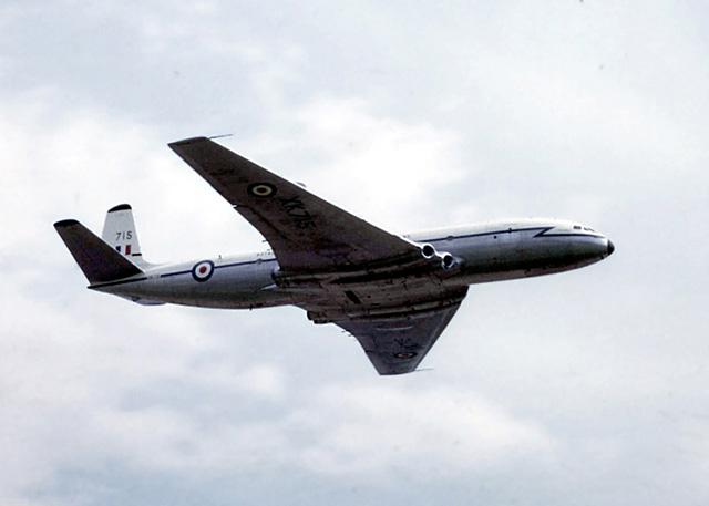
De Havilland Comet, Royal Air Force, 1964, from
Wikimedia Commons
The ideal of having aircraft systems that are fault tolerant simply means that the design should allow for some amount of failure without bringing the entire airplane out of the sky. If you really want to understand the concept, you may have to learn a new language. Some of these terms have specific meanings in engineering parlance:
The term "safe life" means the system or component is designed to last for its finite lifespan and then you expect it to fail. The problem, of course, is some of those components can bring an airplane down.
The term "fail safe" means the designers recognized a failure is possible but the system is designed to be inspectable in service and able to sustain detectable damage before failure compromises the entire system. A fail safe system can also automatically trigger its own replacement to maintain the subsystem's capability.
Some of these terms are borrowed from the computer industry or elsewhere and, as far as I know, are not used in the aviation world:
The term "fault tolerance" is meant to convey the thought a system's individual failure will not be so critical to cause system failure by virtue of its total impact on the system or built in backups and safeguards.
The term "fail passive" means a components failure will automatically remove that component from the system, rendering the failure non-catastrophic.
The Term "fail active" means a component has a built in mechanism or backup to either repair or replace a failed component.
| Fault Type | Fault Tolerant | Fault Intolerant | |
| Systems | "Safe Life" (nonredundant) | ✔ | |
| Systems | Fail Passive (Redundant) | ✔ | |
| Systems | Fail Safe | ✔ | |
| Pilot Error | Fail Passive (undetected) | ✔ | |
| Pilot Error | Fail Passive (detected) | ✔ | |
| Pilot Error | Fail Active | ? | ? |
2
Definitions
Dictionary
- fault tolerance — relating to or being a computer or program with a self-contained backup system that allows continued operation when major components fail (noun)
Source: Merriam-Webster Dictionary
Aviation
- fault tolerance — the ability of an airplane to continue safely flying to landing despite systems failures and pilot error.
Source: Me (or someone else whom I've forgotten)
3
The DeHavilland Comet
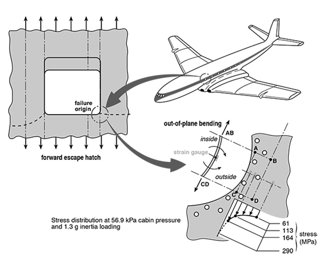
Comet G-ALYU probable failure origin, from
Wanhill, figure 3
- The DeHavilland Comet was the first commercial jet transport, entering service in 1952. The aircraft's performance was much superior to that of contemporary propeller-driven transports. Apart from its speed the Comet was the first high-altitude passenger aircraft, with a cabin pressure differential almost double that of its contemporaries.
- Within two years of entering service, two of the fleet disintegrated while climbing to cruise altitude. Comet G-ALYP was lost on January 10, 1954. Modifications were made to the fleet to rectify some of the items that might have caused the accident.
Source: Wanhill, ¶2
They really didn't have the slightest idea why G-ALYP was lost. Previous Comets had been lost for a variety of reason, usually pilot error. But with G-ALYP, they simply instituted 60+ changes hoping that would address the problem.
- However, Comet G-ALYY was lost on April 8, 1954. The fleet was then grounded. Extensive investigations followed, including most importantly a full-scale repeated pressurization test on an aircraft removed from service, registration number G-ALYU.
Source: Wanhill, ¶2
G-ALYP and G-ALYY were both lost during their climbs, the first made it to 26,000 feet and the second to 35,000 feet. They then suspected pressurization issues. They took an airplane from the line and put it in a large pool of water and started pressurizing it and depressurizing it repeatedly to see what would happen.
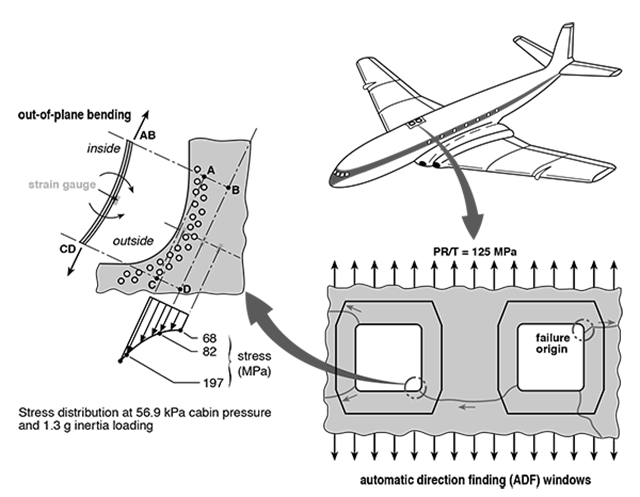
Comet G-ALYU probable failure origin, from
Wanhill, figure 4.
- The test aircraft had accumulated 1,231 pressurization cycles in service. It was tested in a water tank to minimise damage in the event of failure. After 1,825 test pressurizations the pressure cabin failed during application of a proof cycle at 33% higher loading. The failure showed evidence of fatigue cracking that began at the aft lower corner of the forward escape hatch, see figure 3. Additional investigation of wreckage from Comet G-ALYP also showed evidence of fatigue, in this case commencing from the right-hand aft corner of the rear automatic direction finding window, see figure 4.
- The test aircraft was repaired and strain gauges applied to the outside surfaces of several escape hatches and windows. Results for the service and test failure locations are also shown in figures 3 and 4. Swift pointed out that out-of-plane bending would have caused the inside principal stress to be significantly higher, which could well have contributed to the early fatigue failures. This out-of-plane bending would not have been considered in a design analysis for the Comet, nor indeed for subsequent commercial jet aircraft (Swift). However, a full-scale test effectively accounts for it.
Source: Wanhill, ¶2
Nobody predicted greater stress on the corners due to repeated pressurization/depressurization cycles.
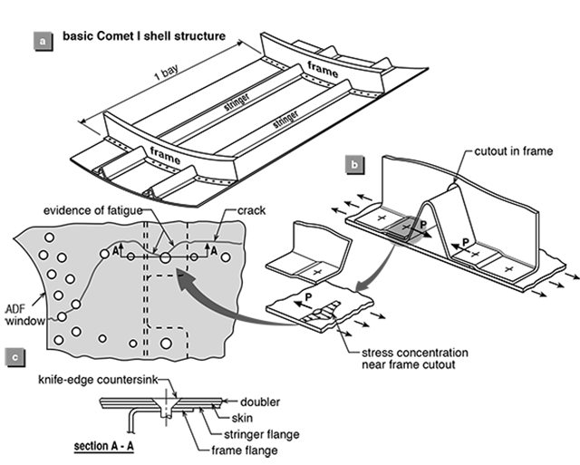
Comet G-ALYP Details of probable failure origin, from
Wanhill, figure 5
- Swift described the Comet pressure cabin structure in more detail, in order to bring out some further important aspects of the service failures. Figure 5 shows the basic pressure shell structure and the probable failure origin for Comet G-ALYP. The basic shell structure had no crack-stopper straps to provide continuity of the frame outer flanges across the stringer cutouts. The cutouts, one of which is shown in figure 5b, created a very high stress concentration at the first fastener. In the case of the probable failure origin for Comet G-ALYP the first fastener was a countersunk bolt, as shown in figure 5c. The countersink created a knife-edge in both the skin and outside doubler. The early fatigue failure may thus be attributed to high local stresses, figure 4, combined with the stress concentrations provided by the frame cutout and knife-edge condition of the first fastener hole, figures 5b and 5c.
- Once the fatigue crack initiated in Comet G-ALYP, its growth went undetected until catastrophic failure of the pressure cabin. Obviously this should not have happened, but Swift provided an explanation from subsequent knowledge. He showed that the basic shell structure of the Comet could have sustained large, and easily detectable, one- and two-bay cracks if they had grown along a line midway between the positions of the frame cutouts. In other words, the basic shell structure would have had adequate residual strength for these crack configurations. However, neither one- nor two-bay cracks would be tolerable if they grew along the line between frame cutouts. For these cases crack-stopper straps would have been needed to provide adequate residual strength.
- The Comet accidents and subsequent investigations changed fundamentally the structural fatigue design principles for commercial transport aircraft. Before – and also during – the Comet era, the fatigue design principles were SAFE-LIFE. This means that the entire structure was designed to achieve a satisfactory fatigue life with no significant damage, i.e. cracking. The Comet accidents, and other experiences, showed that cracks could sometimes occur much earlier than anticipated, owing to limitations in the fatigue analyses, and that safety could not be guaranteed on a SAFE-LIFE basis without imposing uneconomically short service lives on major components of the structure.
- These problems were addressed by adoption of the FAIL-SAFE design principles in the late 1950s. In FAIL-SAFE design the structure is designed firstly – as before – to achieve a satisfactory life with no significant damage. However, the structure is also designed to be inspectable in service and able to sustain significant and easily detectable damage before safety is compromised. These latter requirements were met mainly by employing structural design concepts having multiple load paths, with established residual strength requirements in the event of failure of one structural element or an obvious partial failure.
- Verification of FAIL-SAFE design concepts requires much fatigue and residual strength testing. An essential part of this verification is the study of fatigue crack growth, its analysis and prediction. However, when the FAIL-SAFE principles were first adopted it was not yet required to do full-scale testing. Subsequent experience and knowledge has led to mandatory full-scale testing.
- It is important to note here that not all structural components are amenable to FAIL-SAFE design. The main exceptions are landing gears, usually made from high-strength steels and designed to SAFE-LIFE principles. Going beyond commercial transport aircraft, SAFE-LIFE design is also used for most general aviation aircraft and helicopters, and some military aircraft.
Source: Wanhill, ¶2
4
Examples of fail safe systems
| Fault Type | Fault Tolerant | Fault Intolerant | |
| Systems | Fail Safe | ✔ | |
A fail safe system handles problems automatically without outside intervention, notifies the pilot, and allows the aircraft to continue flying safely. Optimally, the aircraft continues as if nothing had happened. But at the very least, the pilot is left with a flyable airplane and options.
Gulfstream G450 Transformer Rectifier Units
The GV series electrical system is perhaps the most redundant and most fault tolerant electrical system ever designed. It is said that you never have to touch the electrical panel except when you are at the simulator. The DC electrical system is powered by four transformer rectifiers (TRUs) with a fifth, identical TRU just sitting in "ready reserve." If one of the four TRUs should fail, the fifth steps in automatically and notifies the pilot that it has done so.
With the fifth TRU operating the aircraft loses absolutely no capability.
Gulfstream V Series Aircraft Emergency Descent Mode
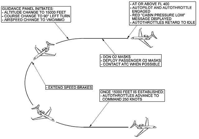
GV Automatic Emergency Descent, from
GV Aircraft Operating Manual, §06-04-00, figure 1.
Many high altitude aircraft, such as the GV, will automatically sense a loss of cabin pressure and execute an emergency descent without pilot interaction. Even if both pilots pass out, the aircraft descends to 15,000 feet and establishes level flight at a safe speed until the pilots regain consciousness.
The aircraft may obviously have other issues to deal with, but the system made it possible for the pilots to survive and live to deal with those problems.
5
Examples of fail passive (redundant) systems
| Fault Type | Fault Tolerant | Fault Intolerant | |
| Systems | Fail Passive (Redundant) | ✔ | |
A fail passive systems failure that is redundant notifies the pilot, and provides the pilot with options so the aircraft may continue flying safely. In some cases, the system may automatically disable itself. Optimally, the aircraft could continue as if nothing had happened. But at the very least, the pilot is left with a flyable airplane and options.
Gulfstream G450 Flight Control Hard Over Protection System
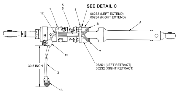
G450 aileron force link, from
G450 Maintenance Manual, §27-13-01, figure 401, sheet 1.
Each axis of the G450 flight control system, for example, is monitored by a "Hard Over Protection System" (HOPS) that continuously compares pilot inputs into hydraulic flight control systems with the resulting output. If there is a significant difference, the actuator is hydraulically depowered, leaving the pilot with manual reversion capability.
Boeing 757 Pitot-Static System
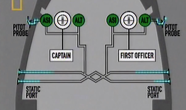
B-757 pitot-static system, from
Mayday, "Flying Blind," 17 Sep 2003
Pitot-static systems are usually considered fault tolerant because they have multiple back ups and are usually monitored electronically. But they can also be fault intolerant because they are often designed to be completely independent of any external sources. The systems can be driven purely by air pressures without any electrical power required. Even some aircraft with glass cockpits simply report the output of the pneumatics of the pitot-static system. With these airplanes, pilots must constantly guard against failures by crosschecking other sources.
In the case of Aeroperu 603, the static ports were covered with tape, leaving the airspeed and altimeter indications in doubt. Many aircraft have electronic comparison monitors, but even these can be fooled. These pilots were fooled by the fact their transponder was reporting the same altitude as their errant instruments, failing to realize the transponder was using outputs of the same faulty pitot-static system. Pilots should understand which of their systems are fault intolerant and tend to fail non-gracefully. Only with added systems knowledge can these faults be detected and dealt with.
More about this: Aeroperu 603.
6
Example of safe life (nonredundant) systems
| Fault Type | Fault Tolerant | Fault Intolerant | |
| Systems | Safe Life (nonredundant) | ✔ | |
A safe life systems failure that is nonredundant might notify the pilot, but more than likely will not. It will at the least reduce the aircraft's capability and could be catastrophic very quickly. Pilots should be aware of these "weak links" and be wary of accepting aircraft systems failures that leave them with redundant vulnerabilities.
If a system can fail under the normal life span of the aircraft and has no backup system, it is non-redundant and can be termed as a single-point-failure system. These non-tolerant systems require careful monitoring and related systems need to be handled with special care, in fear that they might trigger the single-point-failure system to fail. Of course a big problem here is that we often don't know where these systems are.
MD-83 Horizontal Stabilizer

MD-83 stabilizer trim, from
Mayday, "Cutting Corners," 15 Oct 2003
The DC-9 was designed with a single-point-failure stabilizer trim system and that design followed on to the MD-83 and Boeing 717. If the stabilizer jack screws were to fail, the only thing preventing the stabilizer from moving into an uncontrollable position was a single "acme nut." The crew of Alaska Airline 261 did not know this, nobody did, and continued troubleshooting until the part failed. The manufacturer should have placed a warning in the flight manual that because this was a single-point failure system, once it had failed all further attempts to move the stabilizer should have been stopped.
More about this: Alaska Airlines 261.
7
Example of fail active pilot error systems
| Fault Type | Fault Tolerant | Fault Intolerant | |
| Pilot Error | Fail Active | ? | ? |
A fail active pilot error system is one in which the aircraft judges pilot inputs to be faulty, overrides the inputs, and provides corrective action. The corrective action may or may not be overrideable. A stick pusher, for example, actively attempts to recover from a stall. In most aircraft, the pilot can override the pusher if he or she deems that appropriate. In other aircraft, however, no amount of pilot input can override the aircraft's decision to avoid a stall.
Airbus 320 Alpha Protection Mode

Amateur video of Air France 296 just prior to impact,
from Mayday, "Plane vs Pilot"
What about correcting a pilot error automatically, without pilot intervention? This goes to the heart of what some call the "Boeing versus Airbus Philosophy" difference. The Boeing philosophy meaning that the aircraft monitors the pilot and notifies him or her when there is a problem; the Airbus philosophy being that the aircraft can override the pilot's inputs to protect the airplane.
On all modern Airbus planes, starting from the A320 up to the A340, computers prevent the pilot from climbing above 30 degrees (to prevent a stall) or pitch down below 15 degrees (to prevent overspeed). Furthermore, it would not allow the pilot to bank or roll more than 67 degrees or make any maneuvers greater than 2.5 times the force of gravity.
It is a controversial subject. On the face of it, how can having the aircraft automatically prevent a stall be a bad thing? In 1988, one of the first Airbus 320 jets crashed during an air show in Habsheim, France. The pilots planned a low altitude fly by at maximum angle of attack and 100 feet, but for various reasons ended up at 30 feet. When the pilot realized he was at tree top level he commanded full power and got a delayed response from the engines, perhaps due to the restricted air flow caused by the high deck angle. The official accident blames the pilot, but this report was written by the government of France who had a vested interest in the aircraft being exonerated. (It is thought the company would have failed had the aircraft been found causal.) The flight data recorder shows the elevator moved down after the pilot commanded nose up and some contend the aircraft entered the stall protection mode just prior to reaching the trees. There was also a four minute gap in the cockpit voice recorder and photographic evidence the both the flight data recorder and cockpit voice recorder's had been replaced. The French justice system did not buy this and convicted the pilot of involuntary manslaughter.
Depending on where you come down on the "Boeing versus Airbus Philosophy," having a fail active response to pilot errors can be good or bad.
More about this: Air France 296.
8
Examples of fail passive (detected) pilot error systems
| Fault Type | Fault Tolerant | Fault Intolerant | |
| Pilot Error | Fail Passive (Redundant) | ✔ | |
A fail passive pilot error system that is detected is one in which the aircraft judges pilot inputs to be faulty and notifies the pilot, providing the pilot a chance to correct the error.
Gulfstream G450 Runway Awareness Alerting System (RAAS)
The runway awareness and advisory system (RAAS) function supplies improved situational awareness for the flight crew. This improved situational awareness helps lower the probability of runway incursion incidents and accidents by providing timely aural advisory messages to the flight crew during ground taxi, takeoff (including rejected takeoffs), final approach, and landing/rollout operations. The advisories are generated based on the current aircraft position when compared to the location of the airport runways. The airport runways are stored in the threat database (internal EGPWS terrain/obstacle/airport database).
Source: G450 Aircraft Operating Manual, §2B-20-90
9
Examples of fail passive (undetected) pilot error systems
| Fault Type | Fault Tolerant | Fault Intolerant | |
| Pilot Error | Fail Passive (undetected) | ✔ | |
A fail passive pilot error system that is undetected is one in which the aircraft does not detect an error, or if detected, does not notify the pilot of the error. It is up to the crew to detect the pilot error.
Comair 5191 Wrong Runway
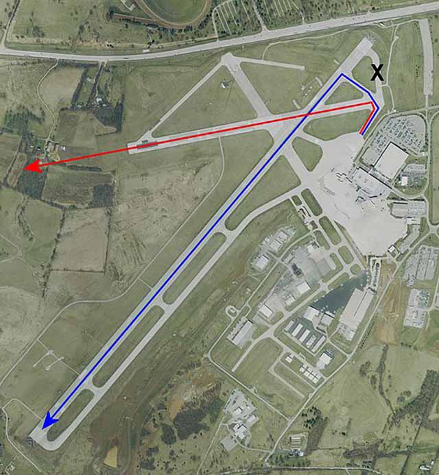
Comair 5191 runway choices
In 2006, the crew of Comair 5191 turned onto the wrong runway at night and ended up killing all on board because the runway they chose was too short. They were not the first crew to ever do this, but with better techniques and systems they will hopefully be the last. This type of error was not detected by technology in their aircraft, but more modern systems turn this kind of error into a fail passive system that at least warns the pilot of the error. A Runway Awareness Alerting System (RAAS) would have notified the crew which runway they were actually on. Even without such as system, the pilot technique of verifying runway heading prior to initiating the takeoff could also have prevented this crash.
More about this: Comair 5191 and callouts.
10
Fault tolerance evaluation
| Fault Type | Fault Tolerant | Fault Intolerant | |
| Systems | "Safe Life" (nonredundant) | ✔ | |
| Systems | Fail Passive (Redundant) | ✔ | |
| Systems | Fail Safe | ✔ | |
| Pilot Error | Fail Passive (undetected) | ✔ | |
| Pilot Error | Fail Passive (detected) | ✔ | |
| Pilot Error | Fail Active | ? | ? |
Of the possible fault modes, the ones we need to pay special notice of are those that are not fault tolerant. By identifying these before flying, we can think through ways to anticipate, avoid, or correct issues before they become problems. The best way to do this is to look at our aircraft's accident history.
Accident History
One of the advantages of flying an aircraft that has been around a few years is you can learn from the experiences of those who came before you. There are several sources of accident history given in the Case Studies section, but individual aircraft manufacturers should be consulted for those that did not end up as mishaps worthy of NTSB investigation.
Systems and Procedures Analysis
Quite often pilots are confronted with "I've never seen that before," or "I've never heard of that before." We need to study our aircraft systems and procedures to anticipate vulnerabilities. Then we can develop techniques to mitigate the vulnerabilities before they become real problems.
11
Evaluating your aircraft
The entire reason for studying aircraft fault tolerance, of course, is to prevent bad things from happening to good aircraft. The Gulfstream G450 provides a good example for evaluation. It is a fairly new aircraft with a spotless mishap record, but it has a rich lineage of aircraft before it to learn from.
Learning from its ancestors
Each generation of Gulfstream seems to answer most of the fault intolerant issues of its parents. As a result, the list is rather short in the G450.
- The G450 has the same ground spoiler system as the GV that led to a destroyed aircraft discussed earlier. As a result, all G450 pilots should adopt the "three green, four in the air" callout and understand that failing the "four in the air" the ground spoilers should not be armed.
- The G450 retains two sets of autothrottle switches that provide an opportunity for inadvertent autothrottle activation during landing. A GIV was destroyed because of this problem. The G450 is less susceptible if the pilot keeps the autothrottles engaged through the landing so that they may enter "retard" mode and automatically disengage with weight on wheels. But the problem remains if the pilot disengages the autothrottles and inadvertently reengages them prior to touchdown. G450 pilots should keep the autothrottles engaged for landing.
More about this: GV N777TY.
More about this: GIV GMAC.
12
Aircraft comparisons
Another method of aircraft analysis is to compare it to similar aircraft from other manufacturers. This serves two purposes:
- How does the other aircraft handle your aircraft's fault intolerant issues?
- What is the other aircraft's mishap history and how would your aircraft have handled these?
The G450 doesn't have any real competition when it comes to range, payload, and speed. But the Falcon 900 series comes close and has an enviable safety record. There are 500 Falcon 900 variants out there, versus 492 GIV and 301 G450 (as of 1Q 2014).
There have been 5 Falcon 900 flight mishaps (5 of 500 = 1 %), the airplane has been in service since 1984:
- 14 Sep 1999: Pilot induced oscillations compounded by aircraft pitch system ended up killing 7 of 10 passengers, though aircraft was repaired. More about this: DA-900B SX-ECH.
- 17 Mar 2000: Aircraft was damaged beyond repair after crew's long landing on short, contaminated runway. N814M
- 23 Mar 2007: Aircraft was substantially damaged, but repaired, after crew's long landing on a wet, downsloping runway. N129KJ
- 10 Jun 2007: Aircraft was substantially damaged after crew's improper trim setting led to aircraft's failure to rotate and subsequent high speed abort. N914DD
- 28 Nov 2008: Aircraft was damaged beyond repair after a mishandled landing. I-FLYI
Although there have been no G450 flight mishaps, there have been 6 Gulfstream IV flight mishaps (6 of 793 GIV and G450 = 0.76 %), the airplane has been in service since 1985:
- 24 Jul 1995: Aircraft was substantially damaged when the left main landing gear disconnected during taxi. From the NTSB Report: "the most likely failure scenario is that the through bolt loosened and the pin fell out allowing the strut to move abnormal to its design function."
- 30 Oct 1996: Aircraft was destroyed after the pilot lost control during takeoff. More about this: GIV N23AC.
- 1 Dec 2004: Aircraft was damaged beyond repair after the pilot inadvertently engaged the autothrottles during landing. More about this: GIV GMAC.
- 12 Feb 2012: Aircraft was damaged beyond repair after the aircraft failed to stop on the runway. More about this: GIV N2SA.
- 13 Jul 2012: Aircraft was damaged beyond repair after the aircraft departed the runway after landing. More about this: GIV N823GA.
- 31 May 2014: Aircraft was destroyed after it failed to become airborne after takeoff and overran the runway. N121JM
References
(Source material)
Gulfstream G450 Aircraft Operating Manual, Revision 35, April 30, 2013.
Gulfstream G450 Maintenance Manual, Revision 18, Dec 12, 2013
Gulfstream GV Aircraft Operating Manual, GAC-AC-GV-OPS-0002, Revision 30, May 13, 2008
Mayday: Pilot vs Plane, Cineflix, Season 9, Episode 3, 8 March 2010 (Air France 296)
NTSB Aircraft Accident Brief, AAB-04/01, Bombardier CL-600-2B16 (CL-604), C-FTBZ, Mid-Continent Airport, Wichita, Kansas, April 14, 2004
Swift, T. 1987, Damage tolerance in pressurized fuselages, 11th Plantema Memorial Lecture, New Materials and Fatigue Resistant Aircraft Design (ed. D L Simpson), pp. 1-77, Engineering Materials Advisory Services Ltd., Warley, UK.
Technical Order 1C-20B-1, C-20B Flight Manual, USAF Series, 1 November 2002
Wanhill, R.J.H., Milestone Case Histories in Aircraft Structural Integrity, National Aerospace Laboratory, NLR-TP-2002-521
Wikimedia Commons, Public Domain Artwork
Please note: Gulfstream Aerospace Corporation has no affiliation or connection whatsoever with this website, and Gulfstream does not review, endorse, or approve any of the content included on the site. As a result, Gulfstream is not responsible or liable for your use of any materials or information obtained from this site.