Your attitude indicator, heading indicator, and turn and slip indicators all use gyroscopes of one sort or another so you might as well understand what's going on behind the curtain. They have been around for a while, the source material for what follows in dated 1966.
— James Albright

Updated:
2014-10-27
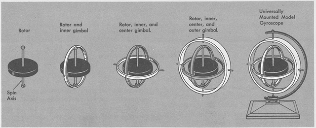
Gyroscope components, from
AFM 51-37, 1966, figure 4-1.
Sure these days your gyros are more likely to be spinning light, but the principle remains the same.
2 — Ring Laser Gyroscopes (RLG)

1
Construction
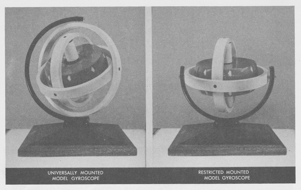
Mountings of the gyroscope, from AFM 51-37, 1966, figure 4-2.
The following requirements are for mechanical gyroscopes and do not apply to laser ring gyroscopes.
- A gyroscope is a cylindrical mass which is mounted to spin rapidly about an axis. There are three major components: the spinning mass or rotor, the spin axis, and gimbals which are used to mount the spin axis. The rotor must meet two basic design characteristics: great weight or density for its size and high spin rate. These two factors largely determine the quality of the gyroscope.
- The power required to drive the rotor and spin it rapidly is provided by either a suction or electrical system.
- There are two types of mountings used in flight instruments — the universal mounting which allow the spin axis to turn and tilt, and the restricted mounting which allows the spin axis only to tilt. Attitude indicators and heading indicators us the universal mounting. Turn and slip indicators use the restricted mounting.
Source: AFM 51-37, 1966, page 4-1.
2
Ring Laser Gyroscopes (RLG)
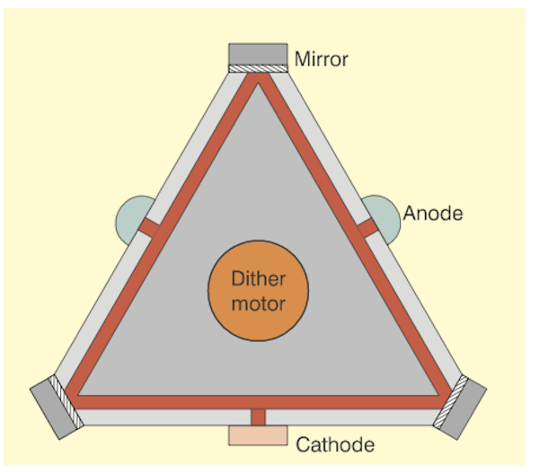
Ring laser gyroscope, from King, figure 8.
- The RLG body is a solid glass block, with three narrow tubes drilled in it. A mirror is placed at each corner, forming a triangular optical resonator path. The tubes are filled with a helium-neon mixture at low pressure. A high voltage (around 1kV) is applied between the cathode and the two anodes, causing a discharge (simply an expensive neon lamp). The discharge provides enough energy to cause regenerative lasing action in the gas, with light beams circulating around the triangular resonator path. In fact, there are two lasers within the same cavity - one with a clockwise (CW) beam, the other counter-clockwise (CCW). When the gyro is at rest, the two beams have the same frequency (typically with a wavelength of 633 nanometres).
- Now consider the block rotating in a CW direction. A photon in the CW beam, starting at the bottom left hand mirror finds, after one traverse of the cavity, that the mirror has moved slightly further away. Thus it sees a slightly increased path length. Similarly, a photon in the CCW beam finds a shorter path length. The difference in path lengths causes a small difference in frequency. By making one of the mirrors partially-transmitting, samples of both beams can be extracted and the frequency difference measured. This is precisely proportional to the applied rotation rate.
- A complication arises at very low rotation rates. The mirrors are not perfect and produce miniscule amounts of backscatter, which couples energy between the two beams. This coupling of energy between two very high-Q oscillators can cause the frequencies to lock together. To overcome this, the dither motor applies a very small oscillatory rotation (about 1 arc-minute peak, at about 400Hz) to the entire block.
Source: King
So you might be asking yourself, how does light bouncing around a set of mirrors duplicate a spinning gyroscope? Here's how I think of it . . .
- A laser (light amplification by stimulated emission of radiation) beam travels at the speed of light and can be timed.
- Two beams are sent at opposite directions and are timed. Movement of the platform will cause the beams to travel further or shorter, affecting the elapsed time.
- The two beams are channeled to a photo detector. If there is no motion in that axis, the two beams are in sync. If there is rotation in that axis, one beam becomes out of phase from the other. The difference can be measured as if it were movement of a gyroscope spin axis.
3
Properties of gyroscopic action
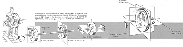
Precession of a gyroscope, from AFM 51-37, 1966, figure 4-3.
The two fundamental properties of a gyroscope used in flight instruments are rigidity in space and precession.
- Rigidity in Space. Newton's first law of motion states that a body at rest will remain at rest, or if in motion in a straight line, it will continue in motion in a straight line unless acted upon by an external force.
- Newton's second law of motion states that the deflection of a moving body is directly proportional to the force applied and inversely proportional to the weight and speed of the body.
- Attitude indicators and heading indicators use the gyroscopic property of rigidity in space.
- Precession. Precession is that property of a gyro which causes the spin axis to be displaced in a direction 90° from an applied force and in the direction of rotor rotation. The two types of precession most affecting aircraft attitude and heading indicators are real precession and apparent precession.
- Real Precession. Real precession is a deflection of the spin axis caused by an externally applied force. In flight instruments, this force is the result of G-forces or acceleration/deceleration caused by turning the aircraft or changing speeds. To generate real precession, the force must attempt either to turn or tilt the spin axis. A force which attempts to turn the spin axis will cause it to tilt. A force which attempts to tilt the spin axis will cause it to turn.
Source: AFM 51-37, 1966, page 4-3.
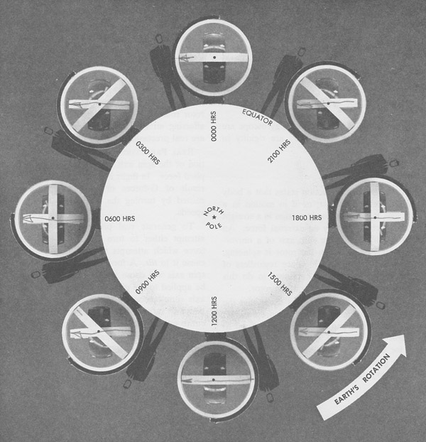
Apparent precession, from AFM 51-37, 1966, figure 4-4.
- Apparent Precession. Because of the gyroscopic property of rigidity in space the spin axis of a universally mounted gyro points in a fixed direction. However, the earth is rotating, turns under the gyro and the spin axis appears to tilt. For example, imagine a gyroscope at the equator with the spin axis horizontal to the earth as shown [in the figure]. The earth turns in the direction of the arrow (counterclockwise) with an angular velocity of one revolution every 24 hours. To an observer on the earth, the spin axis appears to gradually tilt or drift. At the end of 3 hours, the spins axis has tilted 45° and after 6 hours the spin axis has tilted 90° to a vertical position. At the end of 12 hours the spin axis is again horizontal, and at the end of 24 hours it is back in its original position.
- This phenomenon creates the illusion that the gyro has turned over, end for end, and that a complete revolution is made every 24 hours. Actually, however, the gyro has maintained its position in space, and the earth has moved under it. The movement of the earth in relation to the gyro is called apparent gyroscopic precession.
Source: AFM 51-37, 1966, page 4-3.
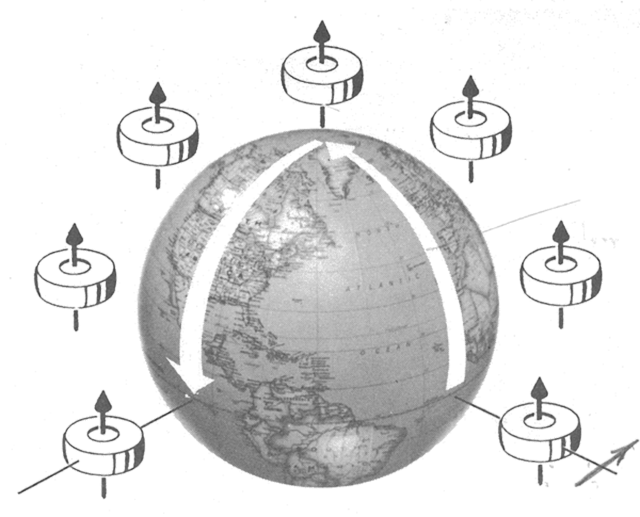
Change in spin axis due to transportation of gyro, from AFM 51-37, 1966, figure 4-5.
- Transportation of the gyro about the earth produces similar results. The changes consist of tilting, turning, or combinations of both.
Source: AFM 51-37, 1966, page 4-3.
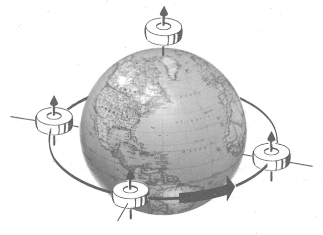
No apparent precession, from AFM 51-37, 1966, figure 4-6.
- Only a vertical gyro located at the poles or a horizontal gyro with its axis aligned north-south located at the equator will not display apparent precession.
Source: AFM 51-37, 1966, page 4-3.
4
Principles of inertial navigation
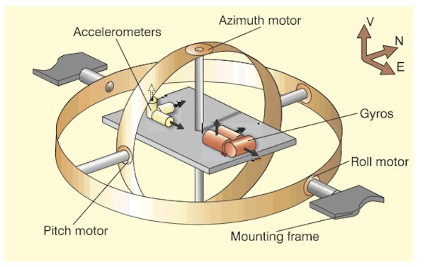
Gimballed Inertial Platform, from , figure 1.
- Consider an accelerometer as an instrument that measures acceleration along a single axis. Integrate the output once, and you have velocity. Integrate again, and you have position - or rather, change of position - along the accelerometer's axis. If you know the direction of travel, you can deduce current position. Inertial Navigation is simply a form of `dead reckoning'. You need to know the starting point - an inertial navigation device/system (I.N.) can't find its initial position on the earth (it can find latitude, with difficulty, but not longitude).
- Take three accelerometers, with their sensing axes orthogonal. Arrange them so that their axes are aligned north-south, east-west, and vertical. To maintain this orientation when the vehicle maneuvers, the accelerometers are suspended in a set of three gimbals that are gyro-stabilized to maintain the direction.
- The gyros, similarly, are single-axis devices, of a type known as `integrating' gyros - that is, they give an output proportional to the angle through which they have been rotated (about their input axes). The gyros are used as the sensing elements in null-seeking servos, with the output of each gyro connected to a servo-motor driving the appropriate gimbal, thus keeping the gimbal in a constant orientation in inertial space.
- Integrating gyros also have what is called a `torquer', a means of precessing the input axis at a rate proportional to input current. This forms a convenient means of cancelling out any drift errors in the gyro, and also provides another function that will be described below.
- The gimbals, as shown, have a bearing at each end. Each has a motor, built around one of the bearings, and at the other end a synchro (an electromagnetic angle-measuring device). No matter how the vehicle maneuvers, the innermost gimbal maintains its orientation in inertial space. The synchro on the innermost gimbal thus measures azimuth (or heading), the synchro on the middle gimbal measures pitch, and that on the outer gimbal measures roll.
- The innermost gimbal can be thought of as a `stable platform' on which are mounted the gyros and accelerometers (although, in practice, it looks like anything but a platform, being a miracle of mechanical packaging). The whole arrangement is generally called a `gimballed platform'.
A gimbal is a mechanism designed to keep an instrument level. It was originally designed to keep a ship's compass horizontal using two concentric rings with pivots at right angles.
Source: King
References
(Source material)
Air Force Manual (AFM) 51-37, Instrument Flying, 20 January 1966
King, A.D., "Inertial Navigation - Forty Years of Evolution," General Electric Company Review, Vol. 13, No. 3, 1998.