By virtue of pure luck, kismet, and serendipity, I started my big airplane experience flying the original version of the KC-135 tanker, a 300,000 pound monstrosity powered by four tiny 9,000 pound thrust engines. The airplane taught the importance of energy management during all phases of flight and learning to cross obstacles to "scrape paint" because that's all you could do.
— James Albright

Updated:
2019-08-13
In the civilian world we have to do better than scrape paint. For a discussion of obstacle climb performance see Departure Obstacle Avoidance. Even without an obstacle, 14 CFR 25 requires our U.S. certified aircraft be able to make certain climb minimums, as shown below.

1
Minimum climb performance
Unless otherwise prescribed, in determining the accelerate-stop distances, takeoff flight paths, takeoff distances, and landing distances, changes in the airplane's configuration, speed, power, and thrust, must be made in accordance with procedures established by the applicant for operation in service.
Source: 14 CFR 25§25.101(f)
In icing conditions, if in the configuration of §25.121(b) with the takeoff ice accretion defined in appendix C:
(i) The stall speed at maximum takeoff weight exceeds that in non-icing conditions by more than the greater of 3 knots CAS or 3 percent of VSR; or
(ii) The degradation of the gradient of climb determined in accordance with §25.121(b) is greater than one-half of the applicable actual-to-net takeoff flight path gradient reduction defined in §25.115(b).
Source: 14 CFR 25§25.105(a)(2)
Takeoff path.
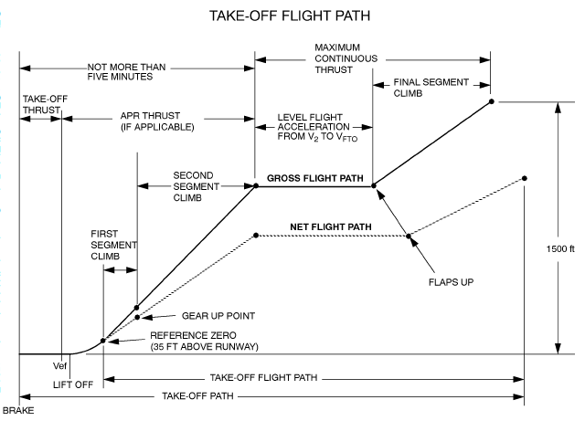
(a) The takeoff path extends from a standing start to a point in the takeoff at which the airplane is 1,500 feet above the takeoff surface, or at which the transition from the takeoff to the en route configuration is completed and VFTO is reached, whichever point is higher. In addition—
(1) The takeoff path must be based on the procedures prescribed in §25.101(f);
(2) The airplane must be accelerated on the ground to VEF, at which point the critical engine must be made inoperative and remain inoperative for the rest of the takeoff; and
(3) After reaching VEF, the airplane must be accelerated to V2.
(b) During the acceleration to speed V2, the nose gear may be raised off the ground at a speed not less than VR. However, landing gear retraction may not be begun until the airplane is airborne.
(c) During the takeoff path determination in accordance with paragraphs (a) and (b) of this section—
(1) The slope of the airborne part of the takeoff path must be positive at each point;
(2) The airplane must reach V2 before it is 35 feet above the takeoff surface and must continue at a speed as close as practical to, but not less than V2, until it is 400 feet above the takeoff surface;
(3) At each point along the takeoff path, starting at the point at which the airplane reaches 400 feet above the takeoff surface, the available gradient of climb may not be less than—
(i) 1.2 percent for two-engine airplanes;
(ii) 1.5 percent for three-engine airplanes; and
(iii) 1.7 percent for four-engine airplanes.
(4) The airplane configuration may not be changed, except for gear retraction and automatic propeller feathering, and no change in power or thrust that requires action by the pilot may be made until the airplane is 400 feet above the takeoff surface; and
(5) If §25.105(a)(2) requires the takeoff path to be determined for flight in icing conditions, the airborne part of the takeoff must be based on the airplane drag:
(i) With the takeoff ice accretion defined in appendix C, from a height of 35 feet above the takeoff surface up to the point where the airplane is 400 feet above the takeoff surface; and
(ii) With the final takeoff ice accretion defined in appendix C, from the point where the airplane is 400 feet above the takeoff surface to the end of the takeoff path.
Source: 14 CFR 25 §25.111
14 CFR 25.111 does not mandate the first, second, third, and final segment nomenclature but does mandate minimum climb performances for these segments at the noted altitudes:
| Engines | 1st Segment | 2nd Segment | 3rd Segment | Final Segment |
|---|---|---|---|---|
| 2 Engine | Positive | 2.4% | Positive | 1.2% |
| 3 Engine | 3.0% | 2.7% | Positive | 1.5% |
| 4 Engine | 5.0% | 3.0% | Positive | 1.7% |
2
Climb gradient versus climb rate
Your aircraft manuals may ask for "climb gradient," given as a percentage, feet per nautical mile, or degrees. Or, you might be asked for a "climb rate," given in feet per minute. There are cheats to make this easy and that is fine, so long as you don't confuse them. But going through the math should make it clearer and prevent using the wrong number when figuring out if you can out climb the rocks. We'll do all this with an example SID.
The important point is the enter your charts with the correct number and do not be confused between gradients such as feet per nautical mile and rates such as feet per minute. The numbers associated with those two are very different, even when they are describing the same flight path.
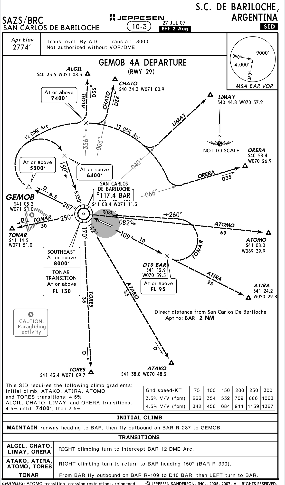
SAZS GEMOB 4A, Jeppesen
Take, for example, the GEMOB 4A at San carlos de Bariloche, Argentina (SAZS). The initial climb gradient to CHATO requires a climb gradient of 4.5% until 7400'. If your flight manual gives you climb gradients given in percentage, you know how to figure this out. But what if your manuals provide another metric? Or what if the SID specifies a different standard? Now let's make it even more confusing. Let's say we can climb out at 150 knots ground speed and the charts says that means we need 684 FPM. Can we do that?
You cannot look at your aircraft's ground speed, such as 150 knots, and find your climb gradient from this chart. The 684 number is a climb rate, a very different number. A gradient describes how high you will be after a given amount of distance. A rate show how fast you will get there.
Gulfstream provides a chart that might help, or it might confuse:
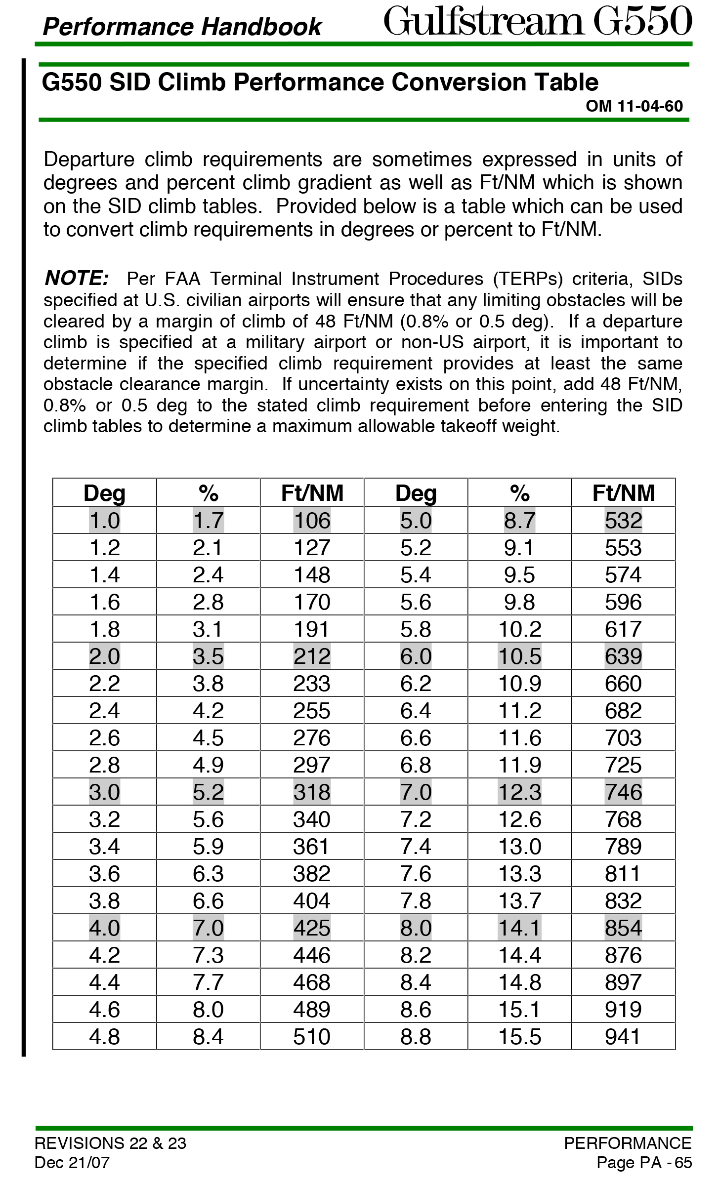
SID Climb Performance Conversion Table, G550 Performance Handbook, p. PA-65
So here we see our 4.5% climb gradient comes to 2.6° or 276 ft/NM.
With the help of that table, we see four different concepts of climb:
- 4.5% — as given on the SID
- 684 fpm — as given on the SID for a ground speed of 150 knots
- 2.6° — as given from the conversion chart, using 4.5% as an entry value
- 276 ft/NM — as given from the conversion chart, using 4.5% as an entry value
It is critically important to realize that all four of these numbers are describing the same flight path, even though they are quite different in magnitude. You cannot enter a chart designed for ft/NM with fpm, for example.
Armed with this knowledge, you should be able to determine from your performance manuals if you aircraft can meet or exceed the required climb. But it is easy to confuse FPM (or FT/MIN) with FT/NM and those numbers are very different. Perhaps a drawing will help.
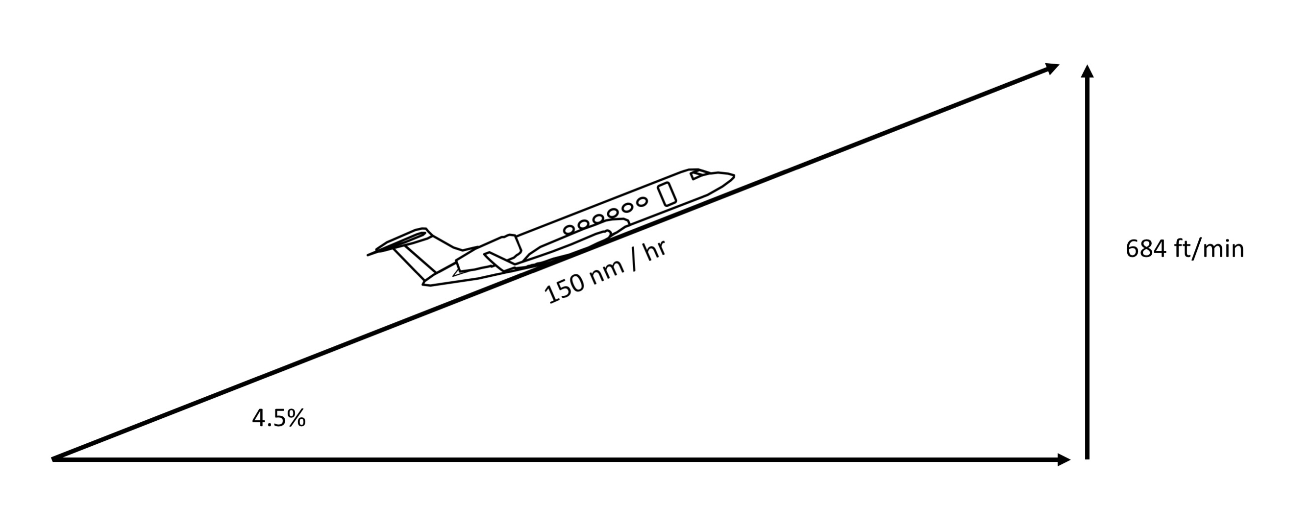
Example Climb Gradient converted to Climb Rate
How do we know this? Algebra . . .
Now let's convert this to an angle, the 2.6° given on the conversion chart:
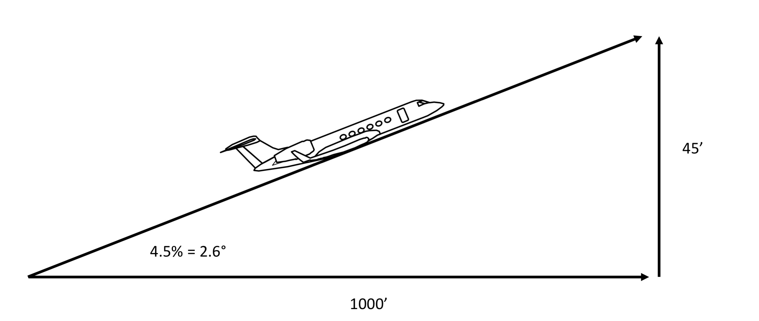
Example Climb Gradient converted to Angle
How do we know this? Algebra first, to determine the height reached at an example distance of 1,000 feet . . .
We can then use trigonometry to find the angle:
Keep in mind there are rounding errors each step of the way and you can come up with slightly different numbers depending on which direction you attack the problem. The conversion chart comes up with 276 ft/nm using the angle as its basis:
But you could have come up with 273 ft/nm using algebra. The numbers are close and the difference is just a rounding error.
3
Gulfstreams, for example
The Gulfstream III, IV, V, G450, and G550 meet the 14 CFR 25 requirements by maintaining second segment performance beyond 1500 feet, eliminating the third and final segments. V2 is flown from 35 feet to at least 1500 feet, which will achieve the 2.4% second segment climb requirement and exceed the required third and final segment minimums. The recommended level off height is a function of the obstacle height and the horizontal distance from reference zero. It is further limited by the operating time on the operating engine at takeoff thrust. This limit is five minutes on the GIII and ten minutes on the GIV, V, G450, and G550. [AFMs Section 5.6]
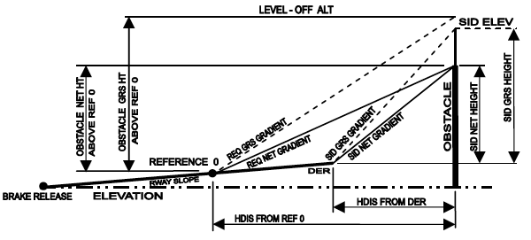
Obstacle and SID parameters, from G450 Airplane Flight Manual, §5.6, page 5.6-1.
- The obstacle clearance procedure is to climb with landing gear retracted, flaps in takeoff position at a speed of V2 to at least 1500 feet above the takeoff surface.
- The minimum level-off height is 1500 feet AAL. When multiple obstacles exist in the takeoff profile, the highest obstacle will dictate the minimum level-off height even if this is not the most demanding obstacle from a required gradient standpoint.
- The maximum level-off height is determined at the intersection of the net 10-minute limit line with the available Reference Climb Gradient line. This limit line was established to ensure that the total time to accelerate from brake release to V2 after recognizing an engine failure at V1 and then climb at V2 with flaps down to the maximum level-off height does not exceed 10 minutes (the engine-out time limit on use of Takeoff Thrust).
Source: G450 Airplane Flight Manual, §5.6.
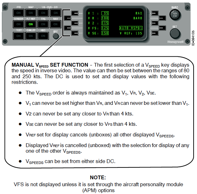
VFS, from G450 Aircraft Operating Manual, §2B-05-30, ¶1.D. page 12.
VFS is not displayed unless it is set through the aircraft personality module (APM) options.
Source: G450 Aircraft Operating Manual, §2B-05-10, page 12.
VFS is not displayed unless it is set through the aircraft personality module (APM) options.
Source: G550 Aircraft Operating Manual, §2B-05-30, ¶1.D, page 12.
For aircraft with JAA certification, VFS is not displayed on the FLT REF menu.
Source: GV Aircraft Operating Manual, §2B-02-20, ¶5.H, page 29.
While VFS is defined for the GIII, GIV, V, 450, and G550 as 1.25 times VSO, it is not used procedurally in the GIV, V, 450, or G550. In those aircraft, takeoff with an engine failed passed V1 calls for flying from V2 to VSE. The entry will be blank on GV aircraft with JAA certification. The entry will appear in the GIV and non-JAA GVs, but it is shown for information purposes only and is not used procedurally.
4
Other aircraft, for comparison
Many aircraft require an intermediate level off prior to 1,500' to clean up and accelerate. The Challenger 604, for example, does use a third segment if the obstacle is below 1500' AGL. The aircraft is flown to obstacle height at V2 at which point it is accelerated, flaps are retracted, and climb is continued at VFTO. If the obstacle is above 1500' AGL, the second segment is extended to obstacle height but no higher than 15,000' MSL or five minutes at takeoff thrust.
Takeoff Flight Path (Gross Level Off Height Less than 1500 Feet), from CL604 Aircraft Flight Manual, §06-04-2.
References
(Source material)
14 CFR 25, Title 14: Aeronautics and Space, Airworthiness Standards: Transport Category Airplanes, Federal Aviation Administration, Department of Transportation
Challenger 604 Airplane Flight Manual, Publication No. CH 604 AFM, Rev 56, Jan 14/05.
Gulfstream G450 Aircraft Operating Manual, Revision 35, April 30, 2013.
Gulfstream G450 Airplane Flight Manual, Revision 35, April 18, 2013
Gulfstream G550 Performance Handbook, GAC-AC-G550-OPS-0003A, Revision 27, July 28, 2008
Gulfstream GV Aircraft Operating Manual, GAC-AC-GV-OPS-0002, Revision 30, May 13, 2008
Please note: Gulfstream Aerospace Corporation has no affiliation or connection whatsoever with this website, and Gulfstream does not review, endorse, or approve any of the content included on the site. As a result, Gulfstream is not responsible or liable for your use of any materials or information obtained from this site.