VRA is one of those numbers that has to be established during certification but one the manufacturer is given so much latitude that it is pretty much meaningless once it is published. The published VRA in the G450, for example, is so much higher than VA, one would be foolish to use it in truly rough air.
— James Albright

Updated:
2014-01-14
That isn't to say it is a number you should ignore. Figuring what is behind the number is a useful exercise and coming up with an idea of what the number really should be can save your airplane's structure if you should happen to find some really rough air.

1
14 CFR 25 design criteria
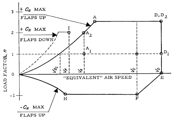
Maneuvering Envelope, from 14 CFR 25, §25.333(b).
A rough air speed, VRA, for use as the recommended turbulence penetration airspeed in §25.1585(a)(8), must be established, which—
(1) Is not greater than the design airspeed for maximum gust intensity, selected for VB; and
(2) Is not less than the minimum value of VB specified in §25.335(d); and
(3) Is sufficiently less than VMO to ensure that likely speed variation during rough air encounters will not cause the overspeed warning to operate too frequently. In the absence of a rational investigation substantiating the use of other values, VRA must be less than VMO—35 knots (TAS).
Source: 14 CFR 25, §25.1517
Theoretically, VRA should be equal to the lesser of points A and H in the diagram and for most airplanes that would be Point H, since most aircraft are capable of more positive than negative load factor. (Load factor is called either n or g.) Aerodynamic theory, however, has to be tempered with other aircraft systems limitations, decreasing the available negative load factor to a point where point H becomes equal to aircraft stall speed. The derivation of VRA, therefore, becomes quite a bit more complicated.
Operating Procedures
(a) Information and instructions regarding the peculiarities of normal operations (including starting and warming the engines, taxiing, operation of wing flaps, landing gear, and the automatic pilot) must be furnished, together with recommended procedures for—
(8) Operation in turbulence for turbine powered airplanes (including recommended turbulence penetration airspeeds, flight peculiarities, and special control instructions);
[Final Rule. Docket No. FAA-2000-8511; Issued 06/15/01] The Federal Aviation Administration amends the airworthiness standards for transport category airplanes concerning airplane operating limitations and the content of airplane flight manuals. Issuing this amendment eliminates regulatory differences between the airworthiness standards of the U.S. and the Joint Aviation Requirements of Europe, without affecting current industry design practices.
Source: 14 CFR 25, §25.1585(a)(8), Amdt. 25-46, Eff. 12/1/78
14 CFR §25.1585(a)(8) was deleted in 2001 to bring our requirements in line with the JAA.
Design speed for maximum gust intensity, VB.
(1) VB may not be less than
where—
VS1 = the 1-g stalling speed based on CNAmax with the flaps retracted at the particular weight under consideration;
Vc = design cruise speed (knots equivalent airspeed);
Uref = the reference gust velocity (feet per second equivalent airspeed) from §25.341(a)(5)(i);
w = average wing loading (pounds per square foot) at the particular weight under consideration.
ρ = density of air (slugs/ft3);
c = mean geometric chord of the wing (feet);
g = acceleration due to gravity (ft/sec2);
a = slope of the airplane normal force coefficient curve, CNA per radian;
(2) At altitudes where VC is limited by Mach number—
(i) VB may be chosen to provide an optimum margin between low and high speed buffet boundaries; and,
(ii) VB need not be greater than VC.
Source: 14 CFR 25, §25.335(d)
The requirement to furnish the pilot turbulence penetration speeds and procedures is gone but the design criteria still exists. If your aircraft manufacturer provides a VRA, or equivalent, it would be helpful to know what the number means. The manufacturer has some latitude with two boundaries:
- VRA must be greater than the 1-g stalling speed of the aircraft in a clean configuration.
- VRA must be less than VMO - 35 knots TAS.
That is a huge margin which leaves the pilot still wondering what is the correct speed for operating in rough air?
2
The aerodynamics of gust loads
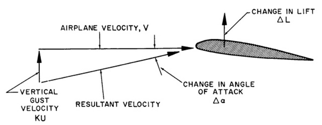
Effect of Vertical Gust, from ATCM 51-3, Aerodynamics for Pilots, Figure 5.2.
- Gusts are associated with the vertical and horizontal velocity gradients in the atmosphere. A horizontal gust produces a change in dynamic pressure on the airplane but causes relatively small and unimportant changes in flight load factor. The more important gusts are the vertical gusts which cause changes in angle of attack.
- The operation of any aircraft is subject to specific operating strength limitations. A single large overstress may cause structural failure or damage severe enough to require costly overhaul. Less severe overstress repeated for sufficient time will cause fatigue cracking and require replacement of parts to prevent subsequent failure.
Source: ATCM 51-3, Aerodynamics for Pilots, pg. 332
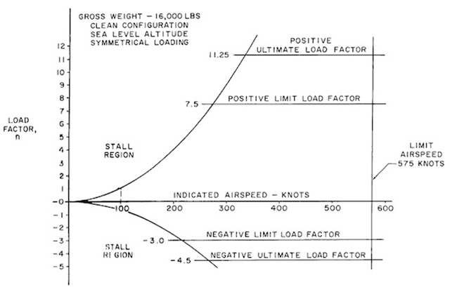
Flight Strength Diagram, from ATCM 51-3, Aerodynamics for Pilots, Figure 5.3.
The operating flight strength limitations of an airplane are presented in the form of a V-n or V-g diagram. This chart usually is included in the aircraft flight handbook in the section dealing with operating limitations.
Source: ATCM 51-3, Aerodynamics for Pilots, pg. 334
There is no V-g diagram in most transport category aircraft, of course. You can build your own, if you are so interested. If you fly your airplane with a degree of finesse you will never need a V-g diagram, to be sure. But it does help if you really want to understand the true VA of your aircraft and how to get the best performance from your wing.
See Operating Flight Strength.
The flight operating strength of an airplane is presented on a graph whose horizontal scale is airspeed (V) and vertical scale is load factor (n). The presentation of airplane strength is contingent on four factors being known: (1) the aircraft gross weight, (2) the configuration of the aircraft (clean, external stores, flaps and landing gear position, etc.), (3) symmetry of loading (since a rolling pullout at high speed can reduce structural limits to approximately two-thirds of the symmetrical load limits) and (4) the applicable altitude. A change in any one of these four factors can cause important changes in operating limits.
Source: ATCM 51-3, Aerodynamics for Pilots, pg. 334
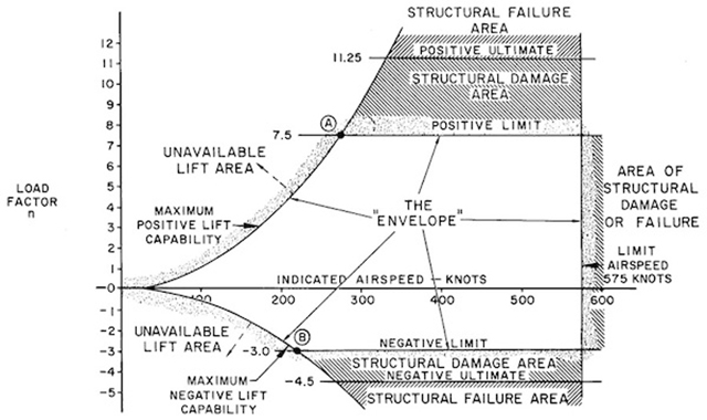
Significance of V-n diagram, from ATCM 51-3, Aerodynamics for Pilots, Figure 5.4.
- The lines of maximum lift capability are the first points of importance on the V-n diagram. The subject aircraft is capable of developing no more than one positive "g" at 100 knots, the wing stall speed of the airplane. Since maximum load factor varies with the square of the airspeed, the maximum positive lift capability of this airplane is 4 "g" at 200 knots, 9 "g" at 300 knots, 16 "g" at 400 knots, etc. Any load factor above this line is unavailable aerodynamically, i.e., the subject airplane cannot fly above the line of maximum lift capability. Essentially the same situation exists for negative lift flight with the exception that the speed necessary to produce a given negative load factor is higher than that to produce the same positive load factor.
- Thus, the airplane in flight is limited to a regime of airspeeds and g's which do not exceed the limit (or red line) speed, do not exceed the limit load factor, and cannot exceed the maximum lift capability. The airplane must be operated within this "envelope" to prevent structural damage and ensure that the anticipated service life of the airplane is obtained. The pilot must appreciate the V-n diagram as describing the allowable combination of airspeeds and load factors for safe operation. Any maneuver, gust, or gust plus maneuver outside the structural envelope can cause structural damage and effectively shorten the service life of the airplane.
- There are two points of great importance on the V-n diagram of [the figure]. Point B is the intersection of the negative limit load factor and line of maximum negative lift capability. Any airspeed greater than point B provides a negative lift capability sufficient to damage the airplane; any airspeed less than Point B does not provide negative lift capability sufficient to damage the airplane from excessive flight loads. Point A is the intersection of the positive limit load factor and the line of maximum positive lift capability. The airspeed at this point is the minimum airspeed at which the limit load can be developed aerodynamically. Any airspeed greater than Point A provides a positive lift capability sufficient to damage the airplane; any airspeed less than Point A does not provide lift capability sufficient to cause damage from excessive flight loads. The usual term given to the speed at Point A is the "maneuver speed," since consideration of subsonic aerodynamics would predict minimum usable turn radius to occur at this condition.
- The maneuver speed can be computed from the following equation:
where
Vp = maneuver speed
Vs = stall speed
N limit = limit load factor
Source: ATCM 51-3, Aerodynamics for Pilots, pg. 334
3
T-38 example
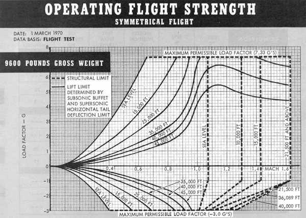
T-38 Flight Envelope, from Technical Order 1T-38A-1, Figure 5-3
At 25,000' and a typical gross weight, the T-38 could best be maneuvered at 0.94 Mach. At this point the wing would not stall and the airplane could deliver 7.33 G. Conversely, if "going negative," the airplane was good for -3.0 G's up to 0.70 Mach. From this you could also conclude that if in rough air, the airplane should be flown no faster than 0.70 Mach because gust loads could be negative as well as positive.
4
G450 Example
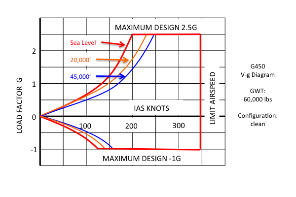
G450 V-g Diagram, Clean, 60,000 lbs
Gulfstream does not include V-g diagrams in their publications, but they can be derived using data available in the G450 Airplane Flight Manual.
See how to do this: Operating Flight Strength.
A typical transport category aircraft is unlikely to have a negative load factor limit greater than -1.0, in fact many specify a negative limit of 0.0 g. (The G450 permits -1.0 in the clean configuration but reduces that to 0.0 g with any flaps extended.) Given a limit of -1.0 g you have the paradox of a best operating speed equal to the aircraft's stall speed:
Flying the airplane at its stall speed in rough air, would satisfy 14 CFR 25, of course, but would hardly be advisable. Gulfstream, fortunately, offers a tighter range of speeds to fly in turbulence:
- Recommended turbulence penetration airspeed is 270 KCAS / 0.75 MT, whichever is lower.
- A minimum speed of 1.5 VS is recommended to maintain adequate buffet margins.
- Severe turbulence will cause large and often rapid variations in indicated airspeed.
Source: G450 Aircraft Operating Manual, §07-02-30-03-40; ¶ 3.A.
An aircraft with a 2.5 g positive load factor limit will have a VA of:
Which is approximately equal to 1.58 times the stall speed. So, for the G-loading, we want the lesser of 1.58 and 1.50 times the stall speed. The best turbulence penetration speed for a G450 is 1.5 x VS, mathematically: VRA = (1.5) VS.

Display Controller VREF
Since we always have a ready display of VREF it would be helpful to know what 1.5 x VS comes to in terms of VREF:
Which means:
And:

Best turbulence penetration speed for a G450 with 0° flaps is its VREF plus 15 percent.
More about this: https://www.code450.com/turbulence-penetration-speed.
Chances are your aircraft flight manual does not offer a V-g diagram but may give a VA maneuvering speed and a turbulence penetration speed. You should understand how these numbers were derived before blindly flying them. Chances are they are numbers built on a unique circumstance and could be hazardous to your health in other circumstances.
A good primer on why this is so: VA - Maneuvering Speed.
References
(Source material)
14 CFR 25, Title 14: Aeronautics and Space, Federal Aviation Administration, Department of Transportation
Air Training Command Manual 51-3, Aerodynamics for Pilots, 15 November 1963
Gulfstream G450 Airplane Flight Manual, Revision 35, April 18, 2013.
Technical Order 1T-38A-1, T-38A/B Flight Manual, USAF Series, 1 July 1978.
Please note: Gulfstream Aerospace Corporation has no affiliation or connection whatsoever with this website, and Gulfstream does not review, endorse, or approve any of the content included on the site. As a result, Gulfstream is not responsible or liable for your use of any materials or information obtained from this site.