We are taught, very early on, that we can best beat an obstacle by flying at VX, our best angle of climb speed. We also learn during primary flight instruction in a simple propeller-driven, reciprocating engine aircraft, that this speed is very close to our stall speed. Both of these lessons are wrong for a jet aircraft.
— James Albright

Updated:
2020-02-10
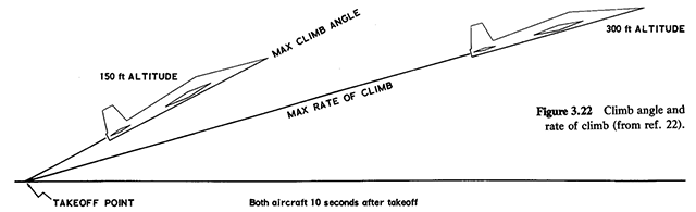
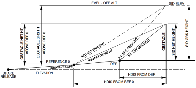
Jet aircraft obstacle clearance,
from Dole, figure 3.21
First off, the VX for a jet aircraft is substantially higher than stall speed. Secondly, the time spent accelerating to this speed in a jet gets you closer to the obstacle. As it turns out, at least for the two-engine aircraft I have flown, V2 works out to be the right speed to beat an obstacle. But if you still need VX, say to make a crossing restriction, having a VX in mind can be helpful.

2
What it really means
Force Analysis
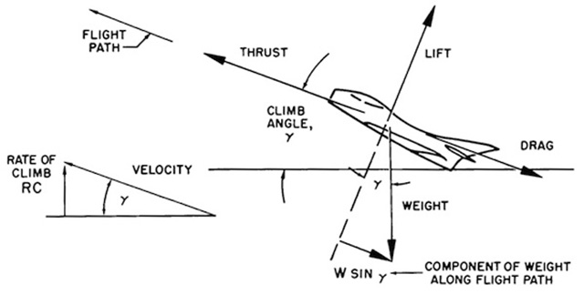
Climb performance, from Air Training Command Manual 51-3, figure 2.21.
- When the airplane is in steady flight with moderate angle of climb, the vertical component of lift is very nearly the same as the actual lift. Such climbing flight would exist with the lift very nearly equal to the weight. The net thrust of the powerplant may be inclined relative to the flight path but this effect will be neglected for the sake of simplicity. Note that the weight of the aircraft is vertical but a component of weight will act along the flight path.
- If it is assumed that the aircraft is in a steady climb with essentially small inclination of the flight path, the summation of forces along the flight path resolves to the following:
where:
T = thrust available, lbs.
D = drag, lbs.
W = weight, lbs.
γ ("gamma") = flight path inclination or angle of climb
Source: Air Training Command Manual 51-3, page 152
Of course some very high performance corporate aircraft, such as the G450, climb at angles where you cannot assume the inclination of the powerplant is negligible. Hence the section devoted to 1950's fighter type aircraft become suddenly applicable to us . . .
- This basic relationship neglects some of the factors which may be of importance of airplanes of very high performance. For example, a more detailed consideration would account for the inclination of thrust from the flight path, lift not equal to weight, subsequent change of induced drag, etc. However, this basic relationship will define the principal factors affecting climb performance. With this relationship established by condition of equilibrium, the following relationship exists to express the trigonometric sine of the climb angle, γ:
- This relationship simply states that, for a given weight airplane, the angle of climb (γ) depends on the difference between thrust and drag (T - D), or excess thrust. Of course, when the excess thrust is zero (T - D = 0 or when T = D), the inclination of the flight path is zero and the airplane is in steady, level flight. When the thrust is greater than the drag, the excess thrust will allow a climb angle depending on the value of excess thrust. Also, when the thrust is less than the drag, the deficiency of thrust will allow an angle of descent.
Source: Air Training Command Manual 51-3, page 152
VX Best Angle of Climb Speed
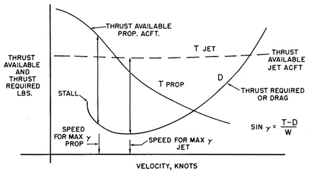
Climb performance, thrust available and thrust required, from Air Training Command Manual 51-3, figure 2.21.
- The maximum angle of climb would occur where there exists the greatest difference between thrust available and thrust required, i.e., maximum (T - D). [The figure] illustrates the climb angle performance with the curves of thrust available and thrust required versus velocity. The thrust required, or drag, curve is assumed to be representative of some typical airplane configuration which could be powered by either a turbojet or propeller type powerplant.
- The thrust available curves for the representative propeller aircraft show the typical propeller thrust which is high at low velocities and decreases with an increase in velocity. For the propeller powered airplane, the maximum excess thrust and angle of climb will occur at some point just above the stall speed. Thus, if it is necessary to clear an obstacle after takeoff, the propeller powered airplane will attain maximum angle of climb at an airspeed conveniently close to — if not at — the takeoff speed.
- The thrust curves for the representative jet aircraft show the typical turbojet thrust which is very nearly constant with speed. If the thrust available is essentially constant with speed, the maximum excess thrust and angle of climb will occur where the thrust required is at a minimum, (L/D)MAX. Thus, for maximum steady-state angle of climb, the turbojet aircraft would be operated at the speed for (L/D)MAX.
Source: Air Training Command Manual 51-3, page 152
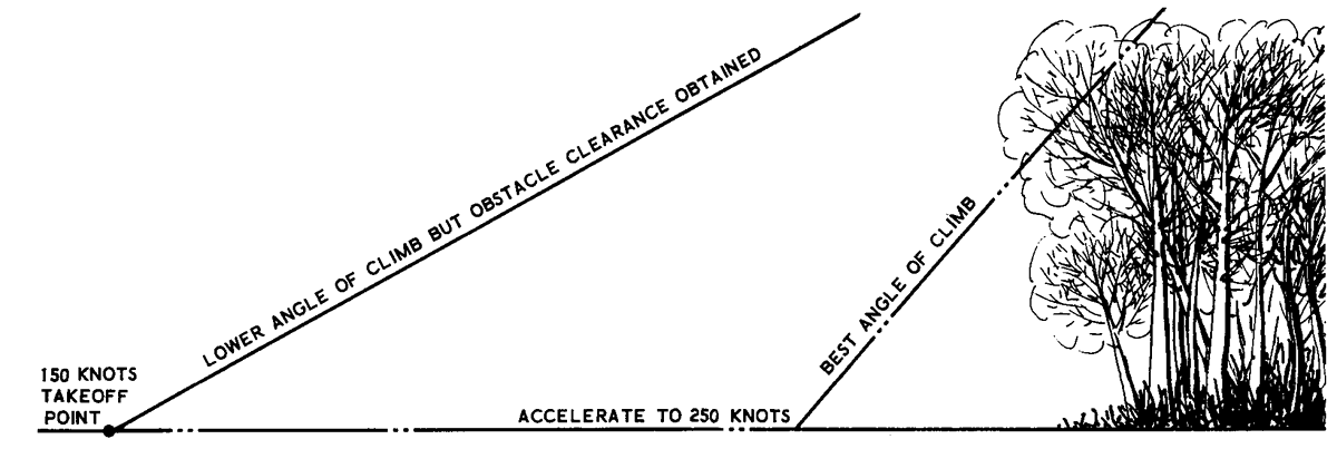
Jet aircraft obstacle clearance trade off, from Dole, figure 3.21
There are two key points here for pilots:
- Pilots transitioning from propeller powered aircraft to jet aircraft must unlearn their instinct to "hang on the props" when trying to achieve a maximum angle of climb. A jet aircraft reaches its best angle of climb, VX, at L/DMAX. That is usually found at 0.30 AOA.
- If trying to clear an obstacle close in with a jet aircraft, there is a trade off to consider. It takes distance to accelerate the aircraft to its best angle of climb speed, getting you closer to the obstacle. There will be a point where you are better off climbing at a lower speed than accelerating. The trade off is considered in flight test and pilots must rely on their flight manuals to make the determination.
More about this: L/DMAX.
3
Gulfstream example
Net takeoff flight path, from G450 Airplane Flight Manual, §05-06-00, figure 1
The trade off between climbing at the speed you have after liftoff and accelerating to a speed approximating VX is made even more complicated when considering an engine failure. Since we always assume the loss of an engine for close-in obstacle clearance, we need to consult our airplane manuals before making this decision. Most Gulfstreams, fortunately, have an extended time allowance on the engines in the event of an engine failure: ten minutes at maximum takeoff thrust. This makes the issue clear for us:
- A close-in obstacle is best addressed by flying at V2 if it can be cleared within ten minutes at takeoff rated thrust.
- If obstacle clearance is determined by a published departure procedure, it may be possible to narrow the horizontal clearance safely while maintaining vertical clearance.
More about this: https://www.code450.com/climb-performance.
More about this: Departure Obstacle Avoidance.
4
How to approximate your VX
Multi-engine aircraft rarely, if ever, publish a VX because it can be a misleading speed. As was seen earlier, the trade off between flying a speed achieved immediately after takeoff and accelerating to VX can make obstacle clearance impossible. There maybe other times, however, when knowing your VX can be helpful. We know a jet powered aircraft's VX is found at L/DMAX but we don't always know what that speed is or at what Angle of Attack (AOA) it can be achieved. But it turns out the AOA for VX is also the AOA for maximum endurance speed so there is a way to approximate it.
To learn how, see: L/DMAX / Performance Charts Holding or Endurance).
Of course much of this theory doesn't seem to translate exactly to many of our aircraft. Why is that? I think it is because very few of us are flying 100% props or 100% jets, which perform differently in the climb. A turbo-prop and a turbo-fan are blends of both. If you have the opportunity to fly the same weights and temperatures over and over again, you can diagram your results and come up with your own VX. Research Test Pilot Dave Fedors has done that for various airplanes, here is his study for the GIII: Approximation of GIII Best Angle of Climb Speed.
References
(Source material)
14 CFR 1, Title 14: Aeronautics and Space, Definitions and Abbreviations, Federal Aviation Administration, Department of Transportation
14 CFR 25, Title 14: Aeronautics and Space, Federal Aviation Administration, Department of Transportation
Air Training Command Manual 51-3, Aerodynamics for Pilots, 15 November 1963
Dole, Charles E., Flight Theory and Aerodynamics, 1981, John Wiley & Sons, Inc, New York, NY, 1981.
Gulfstream G450 Airplane Flight Manual, Revision 35, April 18, 2013.
Gulfstream G450 Aircraft Operating Manual, Revision 35, April 30, 2013.
Please note: Gulfstream Aerospace Corporation has no affiliation or connection whatsoever with this website, and Gulfstream does not review, endorse, or approve any of the content included on the site. As a result, Gulfstream is not responsible or liable for your use of any materials or information obtained from this site.