Despite the old Air Force photograph, I grew up in an environment where one of my first stops in the morning was to a weather office where someone briefed me about what to expect and handed me a few pages tailored for my operation.
— James Albright

Updated:
2021-00-00
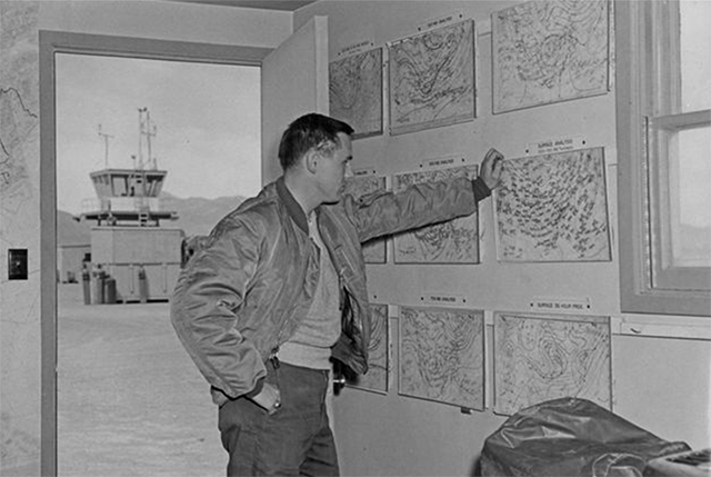
A circa 1960 Air Force weather shop
In the civilian world, if you bothered, you could get similar service by picking up the phone. But these days its all on line. Much better.

1
Decoder
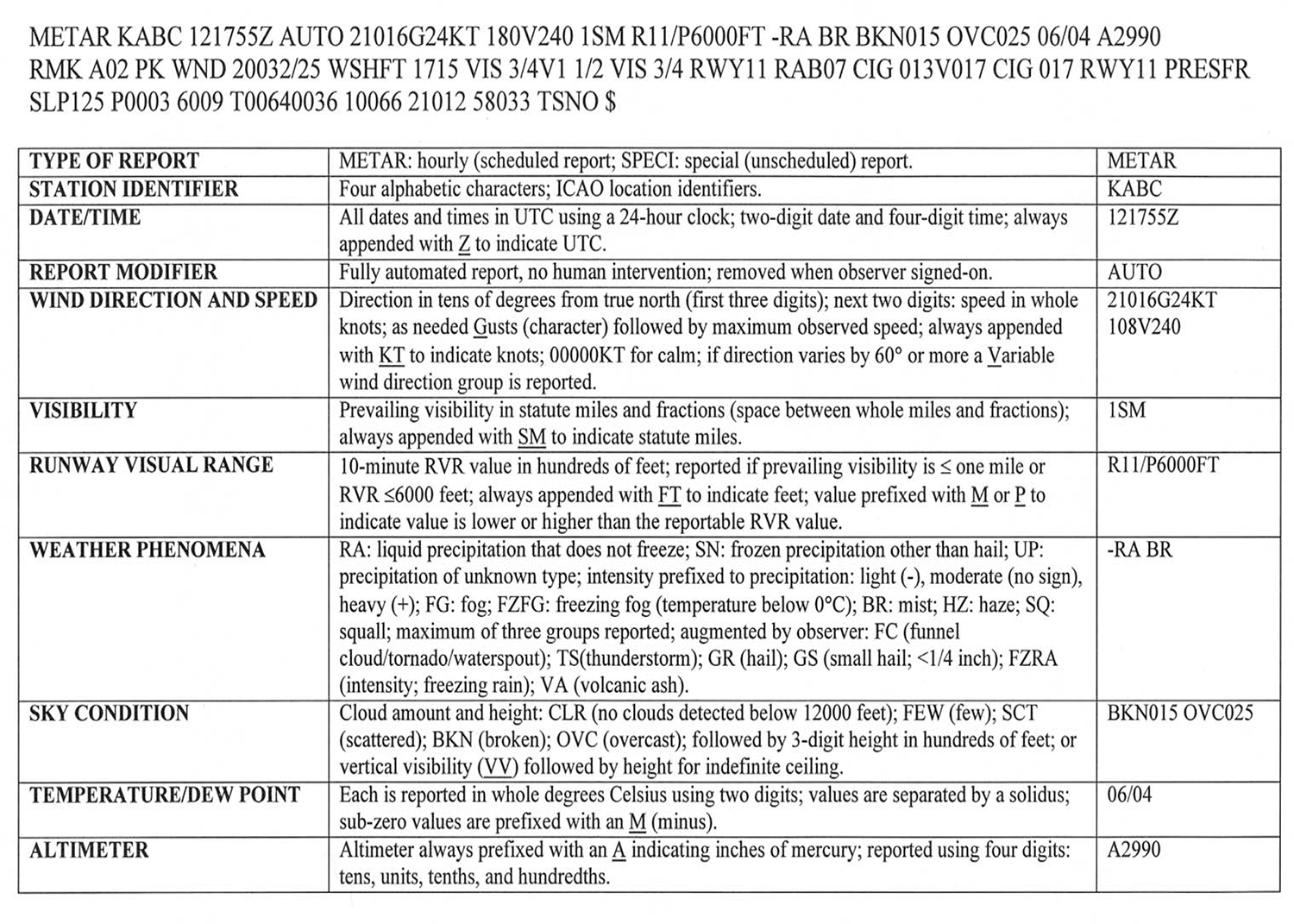
ASOS/AWOS Decoder, AIM, fig. 7-1-7
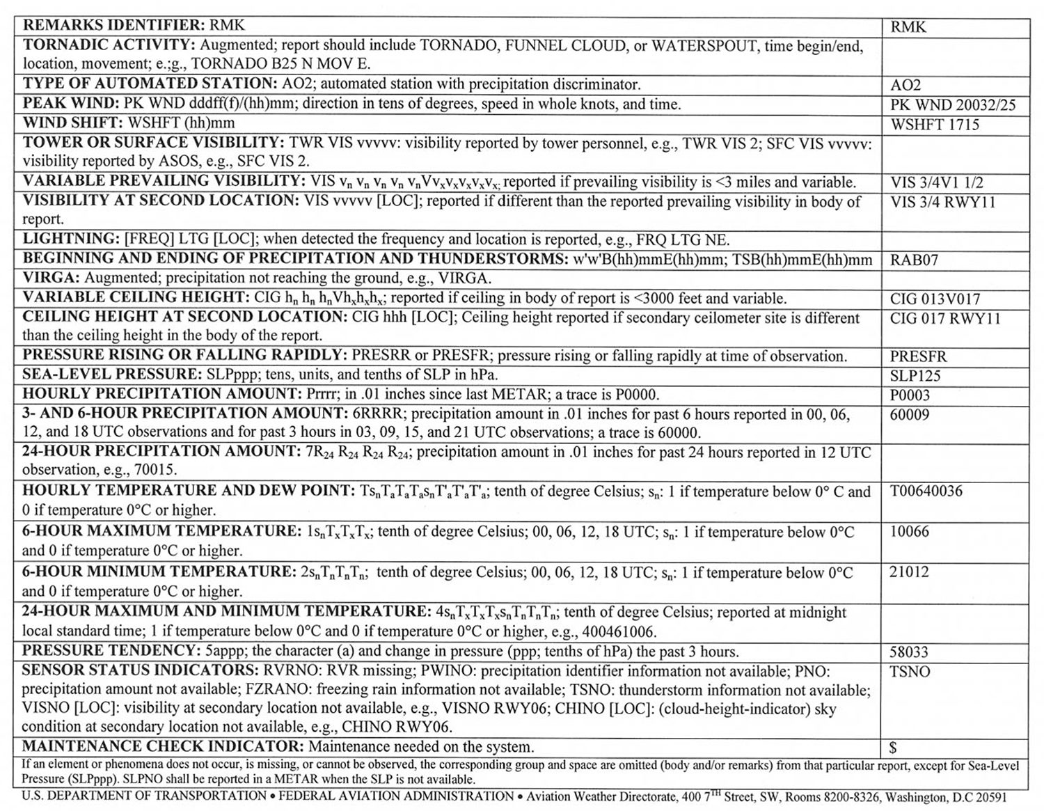
ASOS/AWOS Decoder, AIM, fig. 7-1-8
2
ASOS/AWOS description
d. Automated Surface Observing System (ASOS)/Automated Weather Observing System (AWOS) The ASOS/AWOS is the primary surface weather observing system of the U.S. (See Key to Decode an ASOS/AWOS (METAR) Observation, FIG 7−1−7 and FIG 7−1−8.) The program to install and operate these systems throughout the U.S. is a joint effort of the NWS, the FAA and the Department of Defense. ASOS/AWOS is designed to support aviation operations and weather forecast activities. The ASOS/AWOS will provide continuous minute-by-minute observations and perform the basic observing functions necessary to generate an aviation routine weather report (METAR) and other aviation weather information. The information may be transmitted over a discrete VHF radio frequency or the voice portion of a local NAVAID. ASOS/AWOS transmissions on a discrete VHF radio frequency are engineered to be receivable to a maximum of 25 NM from the ASOS/AWOS site and a maximum altitude of 10,000 feet AGL. At many locations, ASOS/AWOS signals may be received on the surface of the airport, but local conditions may limit the maximum reception distance and/or altitude. While the automated system and the human may differ in their methods of data collection and interpretation, both produce an observation quite similar in form and content. For the “objective” elements such as pressure, ambient temperature, dew point temperature, wind, and precipitation accumulation, both the automated system and the observer use a fixed location and time-averaging technique. The quantitative differences between the observer and the automated observation of these elements are negligible. For the “subjective” elements, however, observers use a fixed time, spatial averaging technique to describe the visual elements (sky condition, visibility and present weather), while the automated systems use a fixed location, time averaging technique. Although this is a fundamental change, the manual and automated techniques yield remarkably similar results within the limits of their respective capabilities.
1. System Description.
(a) The ASOS/AWOS at each airport location consists of four main components:
(1) Individual weather sensors.
(2) Data collection and processing units.
(3) Peripherals and displays.
(b) The ASOS/AWOS sensors perform the basic function of data acquisition. They continuously sample and measure the ambient environment, derive raw sensor data and make them available to the collection and processing units.
2. Every ASOS/AWOS will contain the following basic set of sensors:
(a) Cloud height indicator (one or possibly three).
(b) Visibility sensor (one or possibly three).
(c) Precipitation identification sensor.
(d) Freezing rain sensor (at select sites).
(e) Pressure sensors (two sensors at small
airports; three sensors at large airports).
(f) Ambient temperature/Dew point temperature sensor.
(g) Anemometer (wind direction and speed sensor).
(h) Rainfall accumulation sensor.
(i) Automated Lightning Detection and Reporting System (ALDARS) (excluding Alaska and Pacific Island sites).
3. The ASOS/AWOS data outlets include:
(a) Those necessary for on-site airport users.
(b) National communications networks.
(c) Computer-generated voice (available through FAA radio broadcast to pilots, and dial-in telephone line).
NOTE−Wind direction broadcast over FAA radios is in reference to magnetic north.
4. An ASOS/AWOS report without human intervention will contain only that weather data capable of being reported automatically. The modifier for this METAR report is “AUTO.” When an observer augments or backs−up an ASOS/AWOS site, the “AUTO” modifier disappears.
5. There are two types of automated stations, AO1 for automated weather reporting stations without a precipitation discriminator, and AO2 for automated stations with a precipitation discriminator. As appropriate, “AO1” and “AO2” must appear in remarks. (A precipitation discriminator can determine the difference between liquid and frozen/freezing precipitation).
Source: AIM, ¶7-1-12
3
Sensors
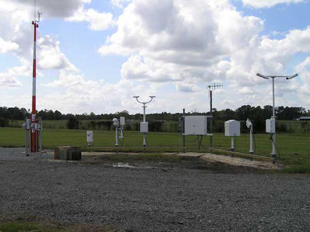
ASOS, from noaa.gov
The ASOS sensors continuously sample and measure the ambient environment, derive raw sensor data and make them available to the collocated DCP. These raw sensor data include visibility extinction coefficients, ceilometer cloud hits, freezing precipitation resonant frequencies and other sensor data. These data are processed as preliminary input into the observation algorithms. The ASOS consists of the following basic complement of sensors:
- Ceilometer, Cloud Height Indicator [CHI] Sensor (one to three sensors per site)
- Visibility Sensor (one to three sensors per site) Precipitation Identification (PI) Sensor
- Freezing Rain (ZR) Sensor (not planned to be included where ZR potential is nil)
- Lightning Sensor (only at selected sites)
- Pressure Sensors (two sensors at small airports; three sensors at larger airports)
- Ambient/Dew Point Temperature Sensor Anemometer (wind direction and speed sensor)
- Precipitation Accumulation Sensor (Heated Tipping Bucket [HTB] Gauge)
Source: ASOS User's Guide, ¶2.1.1
Precipitation Discriminators
There are two types of automated stations, AO1 for automated weather reporting stations without a precipitation discriminator, and AO2 for automated stations with a precipitation discriminator. As appropriate, "AO1" and "AO2" must appear in remarks. (A precipitation discriminator can deter- mine the difference between liquid and frozen/freezing precipitation).
Source: AIM, ¶7-1-12.d.5.
Visibility Sensors
The AV-AWOS experiments in 1979 showed that the values obtained from three visibility sensors (in a 3-mile triangular arrangement) were, in most cases, in close agreement. Further testing supported the premise that only one sensor, located in a representative area, could be used to describe the visibility for an airport area. It was still recognized that sites plagued by advection fog or other visibility discontinuities would require additional sensors. Every airport required a site survey to properly locate the visibility sensor and identify locations that might need additional sensors.
The location of the visibility sensor(s) was critical. The small sampling volume of the sensor dictated that the sensor be located as near to the area of concern as possible. As a result, most primary visibility sensors were placed near the touchdown zone (TDZ) of the primary instrument runway. The actual siting of the sensors had to meet, as closely as possible, the requirements established by the Federal Standard for Siting Meteorological Sensors at Airports, and the clearance requirements of the FAA. This included consideration of local sources of visibility reduction (e.g., plowed fields, snow blowing operations, and smokestacks), the proper sensor height (at least 10 feet), and adequate obstacle clearances.
Source: ASOS User's Guide, ¶4.2
Most airports will have their visibility based on the sensor next to the touchdown zone of the primary instrument runway.
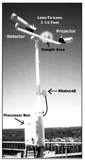
The ASOS visibility sensor [see the figure] operates on a forward scatter principle in which light from a pulsed Xenon flash lamp in the blue portion of the visible spectrum is transmitted twice a second in a cone-shaped beam over a range of angles. The projector and detector are protected with a lens hood and canted down at 15 degrees from the horizon to prevent snow blockage.
Source: ASOS User's Guide, ¶4.2
The sensor isn't looking away from the airport at all, it is sampling the obscuration at its location.
The detector "looks" north to minimize sun glare, particularly from low sun angles near sunrise or sunset. To optimally balance the detection efficiency and differentiation ability of the sensor under varying conditions, a nominal 45 degree horizontal incident angle is set between the projector beam and the detector field-of-view within the sampling volume. This is achieved by offsetting the projector about 45 degrees to the left (i.e., northwest) of the detector. As a result, the projector beam does not directly impinge on the detector lens. Only that portion of the beam that is scattered forward by the intervening medium in the sampling volume is received by the detector.
At some airports a second visibility sensor is placed where unique weather, not necessarily representative of the entire airport, may impact flight operations for a portion of the airport or a particular runway.
One of the main advantages of the visibility sensor is its location at the touchdown zone of the primary instrument runway where it provides a precise visibility value appropriate for that location. Another strength of the sensor is consistency of observations. Under the same weather conditions, an ASOS visibility reported at one site will be identical to the visibility reported at another site because both ASOSs use identical sensors and algorithms. Variations introduced by human observers from such limitations as perspective, sun angle, day and night differences, and poor locations are eliminated.
Source: ASOS User's Guide, ¶4.2
The "advantage" cited is that it will serve the primary instrument runway best and that its readings will agree with the transmissometer. But of course that means it may not be best when evaluating other runways.
References
(Source material)
Aeronautical Information Manual
Automated Surface Observing System (ASOS) User's Guide, National Oceanic and Atmospheric Administration, March 1998