I started flying Boeing 747's the year of this mishap and the "why" was a mystery for a while but the community banded together and immediately thought they understood "how" to survive the circumstances. Of course they were wrong. So let's tackle the "how" before we get to the "why," because the "why" also explains the reason the "how" doesn't work. Confused? Good, now you are in the right mind-set to tackle this case study.
— James Albright

Updated:
2016-07-10
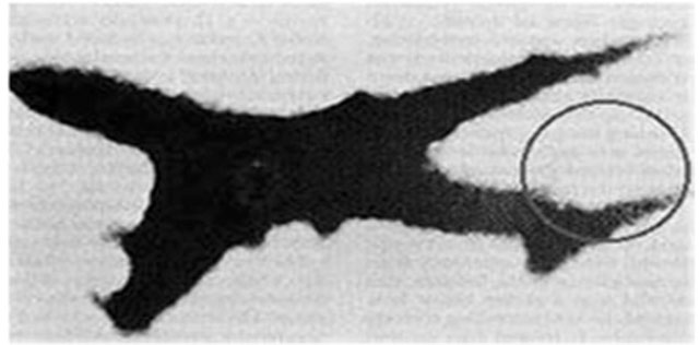
The accident aircraft flying over Okutama,
from Report, Photo 124.
How
The flight controls on the Boeing 747 are hydraulically powered with no mechanical backup. The airplane had a great reputation and to the date of this mishap, there had never been a total failure of the flight control system. Each engine drives a separate hydraulic system, AND each control surface has two hydraulic sources, AND each axis has multiple surfaces, even the rudders. The two rudders were each powered by two hydraulic systems, a total of four systems. What we didn't realize was that all four lines had a common path to the tail.
A photo of the crippled airplane shows it was missing its tail and it became apparent the damage took enough hydraulic plumbing to render every flight control on the airplane useless. (Boeing has since installed fuse plugs upstream of this area so a similar rupture will not result in the same loss.)
We in the Boeing 747 world realized our four engines below swept wings gave us the ability to control roll and pitch with engines alone. You could vary left engine thrust against right engine thrust for roll as well as inboard thrust versus outboard thrust for pitch. So we smugly believed we would have done better than these hapless Japan Air Lines pilots, even though simulator test proved getting the airplane onto a runway was extraordinarily difficult.
But what we didn't realize is that without the vertical fin the airplane was highly susceptible to Dutch roll which is normally confronted by an electronic yaw damper or manually through the ailerons. It would be next to impossible to dampen Dutch roll with differential thrust. Add to all that, the aircraft so oscillating would also enter phugoid cycles, that is, it would pitch up and lose speed causing the nose to drop and gain speed, which then cause a pitch up and so on. This is next to impossible to dampen without an elevator. So these pilots did a very good job controlling the airplane for as long as they did.
Why
The airplane suffered a tail strike in 1978, damaging much of the airplane, including the aft pressure bulkhead. Japan Air Lines hired Boeing to make the repairs. One of the repairs didn't go as planned: a manufactured replacement section of the aft pressure bulkhead did not extend far enough to allow a double row of rivets. This could have been the result of other undetected deformations to the structure or just the way the airplane was supported structurally during the repair. A Boeing engineer devised a work around that involved a metal splice wide enough to join sections with a double row of rivets.
The actual repair, however, used a single row of rivets. This is believed to have weakened the connection by 70 percent.
The airplane flew for another seven years as the metal of the splice and joined sections started to crack and finally gave way in 1985.
When the aft bulkhead gave way, pressurized air entered the vertical fin causing the skin to rupture and peel away. This caused the top of the vertical fin to separate, taking both rudders with it and venting all four hydraulic systems. The flight controls lost all power and the airplane was momentarily controllable using differential thrust. But without the vertical fin the airplane's Dutch roll and phugoid oscillations made the airplane uncontrollable.
So I would contend that are not any flight lessons here at all, the ruptured bulkhead turned the airplane into a uncontrollable projectile. The lessons here are for mechanics to follow repair manuals to the letter, question any deviations from those manuals, and to show up for work well rested and alert. The lessons go deeper than that, see: Maintenance Malpractice.

1
Accident report
- Date: 12 AUG 1985
- Time: 18:56
- Type: Boeing 747SR-46
- Operator: Japan Air Lines
- Registration: JA8119
- Fatalities: 15 of 15 crew, 505 of 509 passengers
- Aircraft Fate: Destroyed
- Phase: En route
- Airport: (Departure) Tokyo-Haneda Airport (HND/RJTT), Japan
- Airport: (Destination) Osaka-Itami Airport (ITM/RJOO), Japan
2
Narrative
Seven Years Before
Instruction issued for correction and actual work of splice, from Aircraft Accident Investigation Commission Report, Attachment 1, figure 3.
- The aircraft, when landing at Osaka International Airport at approximately 1501 hours June 2, 1978 as JAL scheduled flight number 11S (Tokyo to Osaka), was substantially damaged by contact of its lower part of the aft fuselage with the runway, but no fire occurred.
- The aircraft was inspected in accordance with part of the Hard Landing Inspection Phase 1 and 2 in JAL's Maintenance Regulations, and a more detailed inspection was conducted on the damaged portions. Major damage [included . . . the] aft pressure bulkhead dome (4 to 8 o'clock) webs [which were] deformed.
- In the work to attach the new lower half of the aft pressure bulkhead, firstly, the lower half of the bulkhead was attached to the airframe side at the Y chord portion, then. to connect it to the upper half of the aft pressure bulkhead on the airframe side, rivet holes were bored along the web edge of the lower half of the bulkhead, making them match the existing rivet holes of the upper half bulkhead.
- In the inspection by the inspector of the repair team after the completion of the work above, edge margin of less than value specified in the structural repair manual was found around the rivet holes for almost all area of L18 joint on the left side of the lower half of the aft pressure bulkhead.
Source: Aircraft Accident Investigation Commission Report, Attachment 1
There should have been enough metal overlapping each section to allow two rows of rivets, spaced an inch apart, to create a strong, two-row rivetted joint. For some reason there wasn't enough overlap. (The reasons are discussed below, under Analysis.)
- To compensate for the discrepancy above, a rework disposition was given from the engineer of the repair team that a splice plate be inserted. as shown on the left side of Attached figure-3 of Attachment 1, between webs insufficient in edge margin.
Source: Aircraft Accident Investigation Commission Report, Attachment 1
The splice is the shaded metal. If you look on the left side of the figure, notice there are two rivets going through the upper dome and the splice, and the lower dome and the splice.
- Irrespective of such rework instructions having been issued, in the actual repair work, a short splice plate and a filler were used as shown on the right side of the attached figure above, instead of a single splice plate, with the result that the connection for two bays between the 1st strap and the 3rd strap on the left side became a one-row riveted connection, instead of the two-row riveted web connection to be made between the upper half and the lower half of the aft pressure bulkhead. The splice plate and the filler were manufactured from the removed old bulkhead.
Source: Aircraft Accident Investigation Commission Report, Attachment 1
The work actually performed ended up with a narrower splice that has rivets going through the lower dome and splice in two rows (properly) but only once through the upper dome and the splice (improperly). A second splice is added that doesn't add any structural strengthening at all.
- This work was carried out on June 26, and completion inspection by the inspector of the repair team on June 27, but the inspector could not find the above results.
Source: Aircraft Accident Investigation Commission Report, Attachment 1
We have no idea why this work was done this way; it could have been a mistake followed by an effort to disguise the mistake, or perhaps it was just a misunderstanding. Whatever the reason, the weaker joint went undetected. The airplane flew for the next eight years, each pressurization cycle theoretically weakening the joint until cracks developed and then finally gave way.
The Day of the Crash
- At 1824:35 hours just before the aircraft reached 24,000 feet, heading towards Seaperch and approaching east coast of South Izu Peninsula. the aircraft was brought into an abnormal situation which greatly affected continuation of the flight. At the same time, a loud noise like a "boom" was heard. Immediately followed by an utterance of "squawk 77" (meaning emergency code number 7700 of ATC transponder) by both the captain and the copilot. Then, at 1825:21 the captain requested Tokyo Control clearance to descend to and maintain 22,000 feet, and to return to Haneda (Tokyo International Airport) on account of occurrence of such an abnormal situation. At 1825:40 the aircraft requested radar vector to Oshima. To this request, Tokyo Control inquired which was desired, right or left turn for change in heading for Haneda, and received the response from the pilot that he intended to make a right turn. Tokyo Control, accordingly, issued instructions to fly on a magnetic course of 90° after making a right turn for radar vector to Oshima, which was acknowledged by the aircraft at 1825:52.
- At about this time. unusual phugoid and dutch roll motions began, and these phenomena accompanied by large or small motions continued until just before the crash. At 1827:02 Tokyo Control confirmed the declaration of an emergency and then asked "What is the nature of the emergency?" but received no response from the aircraft. At 1828:31 Tokyo Control instructed again the aircraft to "take a magnetic course of 90* for radar vector to Oshima" but the response "now uncontrollable" was received from the aircraft at 1828:35.
Source: Aircraft Accident Investigation Commission Report, ¶2.1
The aircraft appeared to be wandering and the controller again called 123 and gave it further heading instructions. News of their distress had gotten to JAL's headquarters and the company called 123 on the company frequency and were told "Ah . . . the R5[cabin] door is broken. Ah...we are descending now."
- At approximately 1848 hours the aircraft turned to the left at an altitude of about 7,000 feet over the vicinity of Oku-Tama Town, Nishi-Tama Gun, Tokyo, and flew WNW gradually climbing, and after reaching about 13.000 feet at about 1853 hours it started again a descent, and again transmitted "uncontrollable" at 1853:31. At about 1854:19, the aircraft switched over communications to Tokyo Approach Control (hereinafter referred to as "Tokyo Approach") at an altitude of 11,000 feet by an instruction of Tokyo Control. At 1854:25 the aircraft requested its position, to which Tokyo Approach gave "55 nautical miles NW of Haneda and 25 nautical miles west of Kumagaya", which was acknowledged by the aircraft at 1854:55. Then, at 1855:05 Tokyo Approach transmitted "both Haneda and Yokota are available", to which acknowledgment was made by the aircraft. After this, there was no response from the aircraft to calls of Tokyo Approach as well as Yokota Approach Control.
- According to statements of eye-witnesses (4 persons) at points 3 to 4 kilometers SSW of the crash point. "The aircraft flew in buzzing from Oku-Tama area located to the ESE at quite a low altitude and slow speed, slightly nose-up. The aircraft passed overhead, and made an abrupt right turn short of Mt. Sanpei (elevation 1.700 meters) situated to the NW and flew toward Mt. Mikuni (elevation 1,828 meters) located to the ENE. Then. about the time the aircraft would have passed Mt. Mikuni, the aircraft suddenly plunged into a dive banking to the left to NW direction, and went out of sight behind the mountain. Thereafter, smoke and flashing lights were seen emanating from behind the mountain."
Source: Aircraft Accident Investigation Commission Report, ¶2.1
3
Analysis
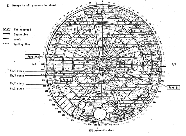
Damage to aft pressure bulkhead, from Aircraft Accident Investigation Commission Report, Figure 32
- Reconstruction was conducted on the airframe wreckage aft of the vicinity of BS2200 in the investigation of wreckage of the aircraft on the assumption that an irregularity occurred in the aft airframe during the flight, from the fact that the vertical fin and a portion of the aft fuselage were discovered from Sagami Bay as well as from the records of DFDR and CVR.
- The aft pressure bulkhead, as shown in the damage chart (Attached Figure - 32), was broken into six main parts, with much complex damage to lower parts.
- Part 1 [ . . . ] the fracture surface was in such a state as the fracture would have been caused by tearing.
- Part 2 [ . . . ] estimated to have been caused by tension.
- Part 3 [ . . . ] estimated to have been cause by peel-off or tear-off.
- Part 4 [ . . . ] were fractured on a circumstance [ . . .]
- Part 5 [ . . . ] estimated to have been caused by tearing or peeling.
- Part 6 [ . . . ] The fracture at R6 joint was caused by tension at the rivet row, but fractures at R12 reinforcement and the lower portion were estimated to have been caused by tear-off. The outer margins were connected to the fuselage skin by the Y chord.
- At L15 joint the lower web edge had been cut off between the first and the third strap about 1.050 mm along the web edge with a width of about 20 mm at right angles thereto. The cut-off portion expressed in rivet numbers was from No.30 to No.83.
- In the cut-off position, an aluminum filler about 0.9 mm in thickness had been inserted and riveted to the stiffener together with the upper web. The cut-off of the lower web edge was made in the repair work related to the accident which occurred to the aircraft June 2, 1978.
Source: Aircraft Accident Investigation Commission Report, ¶2.1.5
- Along L18 splice of BS2360 aft pressure bulkhead, fatigue cracks emanating from a number of rivet holes were recognized by electron microscopic observation.
- L18 splice is the portion where the new and old components of the pressure bulkhead were spliced together in the repair work following the accident at Osaka International Airport. The splice was composed of 2 different types of splice: splice by two-row riveting and splice by one-row riveting.
- With regard to the propagation of fatigue cracks, the crack propagation rate for a one-row riveted splice has been calculated to be more than twice as fast as the rate for a two-row riveted splice.
- The number of pressure cycles (number of flights) required for fatigue cracks to propagate to the length they were in the accident aircraft is calculated to be more than 10 thousand.
- Estimation on Sequence of Rupture
- Since bay 2 and bay 3 were of one-row riveting, the stress on the hole edge was high, and judging from the behavior of fatigue cracks existent at hole edges, the fatigue crack was initiated and propagated on the rivet hole in a comparatively early period after the repair was made for the accident at Osaka International Airport. Fatigue cracks were initiated also on rivet holes of the webs overlapping with the 1st strap, the 2nd strap and the 3rd strap.
- Following the propagation of fatigue cracks from rivet holes in bay 2 and bay 3, fatigue cracks were initiated and propagated on the upper side rivet hole edges (subjected to higher stress than lower side rivet hole edges) located above the two-row riveting on both bay 1 and bay 4 which are of the two-row riveting structure.
- Bay 2 having fatigue cracks was fractured by a estimated cabin differential pressure of 8.66 psi.
- In bay 3, fracture started from the outboard portion where fatigue cracks concentrated, ending in total fracture.
Source: Aircraft Accident Investigation Commission Report, ¶3.1
It appears the cracks started soon after the 1978 repair and continued to grow with each pressurization cycle.
- It is conceivable that the vertical fin may be ruptured when part of the pressurized cabin air, which flows out due to rupture of the aft pressure bulkhead, rushes into the vertical fin, resulting in a rise of about 4 psi in the internal pressure.
- When the internal pressure rises about 4 psi, the fixture between the stringer and the rib chord near the top of the aft torque box is fractured. When one fixture between the stringer and the rib chord is fractured, it induces similar fracture of neighboring fixtures.
- When the stringer and the rib chord are disconnected. the skin of the aft torque box inflates in a pillow shape due to a pressure differential between the outside and inside, causing the rib to buckle, with a result that the skin inflates further and a peel fracture Is caused at the fixture between the skin and the spar chord. When such peel fracture occurs at a location, the skin starts to be peeled off for a considerably wide range, aided by aerodynamic force of the external air flow.
- The aft torque box loses its function as a major structural component, giving rise to collapse of the rear spar, and to separation of the rudder supported by the spar, as well as to damage of the rudder-related control cable system and the rudder related hydraulic lines.
Source: Aircraft Accident Investigation Commission Report, ¶3.1
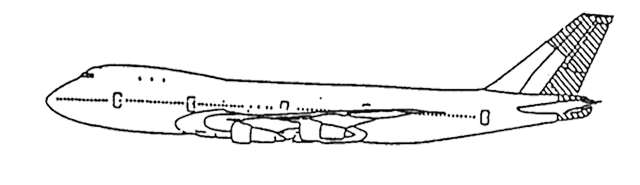
Lost portions of vertical fin, from Aircraft Accident Investigation Commission Report, Figure 15.
They lost both rudders, the top of the vertical fin, and the aft-most portion of the tail. The airplane has four hydraulic systems, two go to the top rudder and the other two to the bottom rudder. The severed hydraulic lines left the airplane with no hydraulic systems at all. The aircraft does not have cable back ups to the flight controls, so the aircraft at this point was only controllable by use of differential thrust. Since the engines are mounted below the wings, the aircraft can be rolled using left versus right thrust. Since the wings are swept, pitch can be altered using inboard versus outboard thrust. This is quite a challenge in a simulator with an airplane that still has its tail. This aircraft, however, would have been difficult to control even if they still had hydraulics.
- Loss of the empennage/fin brought about decrease in stability due to change in the aerodynamic shape and deterioration of the control due to loss of rudder surface, damage to control cables, loss of hydraulic pressure, etc.
- Throughout the flight after the occurrence of the abnormal situation, phugoid mode was excited, together with dutch roll mode. Regulating altitude by attitude control is the fundamental requirement for suppressing phugoid motion. [ . . . ] Under such conditions, normal attitude control should have been impossible.
- Judging from the response of the aircraft as recorded on DFDR, it is considered that the aileron have functioned for more than one minute, but thereafter did not at all due to loss of hydraulic pressure in the same manner as the elevator.
- Suppressing of dutch roll mode by use of the differential thrust between the right and left engines is estimated practically impossible for a pilot.
Source: Aircraft Accident Investigation Commission Report, ¶3.1.7
- Repair of damage following the accident at Osaka International Airport in 1978 as well as operations and maintenances/inspections of the aircraft thereafter.
- It is acknowledged to have been proper that the repair work related to structures of the aircraft was accomplished by the Boeing Company for JAL by the contract, because the aircraft was manufactured by the company and that the company had much experience in the repairs with satisfactory achievements in the past.
- When the lower half of the aft pressure bulkhead deformed by the accident was removed and was being replaced by the new one in accordance with the repair plan, it was found by an inspector of the Boeing Company that there were locations where the edge margin around the rivet holes on the splice surface (L18 splice) between webs of the upper half and the lower half of the bulkhead was less than value specified in the structural repair manual.
- The reduced edge margin is estimated to have been caused by one or a combination of the following:
- disorder in alignment of rivet hole rows existent on the upper half of the aft pressure bulkhead,
- deformation of the upper and the lower half of the bulkhead which is of a thin plate structure,
- deformation of an aft portion of the fuselage due to shock at the time of the accident,
- deformation caused by removal of part of an aft portion of the fuselage for the repair work, and
- short dimensions of the cut end of the upper edge of the web of the lower half of the bulkhead.
- To prevent the airframe from deforming. the aft fuselage was supported by additional jacks: nevertheless. some deformation might have remained in the aft fuselage. In this connection. it might have been possible to use special tools in order to prevent the fuselage from deforming and to facilitate the installation of the lower half of the aft pressure bulkhead. but no such work was carried out.
Source: Aircraft Accident Investigation Commission Report, ¶3.2.2
The part didn't fit properly so they tried to address fuselage deformation due to the way the airplane was sitting, but that didn't work. What they did next doesn't make sense.
- From this, it is considered that concern against deformation of the aft fuselage. etc. was somewhat insufficient in the repair work of the aft pressure bu1khead.
- As a corrective measure of the shortage of edge margin mentioned above, an instruction to make a splice joint by inserting a splice plate was issued by an engineer of the repair team of the Boeing Company. The instruction is considered to have been virtually pertinent.
- During the repair, work was carried out in which one splice plate narrower than described in rework instructions, and one filler were applied, instead of one splice plate. No written record. however. was found to the effect that such work was done.
- It is estimated that during this rework, part of L18 splice which should have been spliced by two-row rivets became spliced by one-row rivets, with the result that the strength of this part decreased to about 70% of the original strength. From this. it is estimated that these portions was brought under a condition susceptible of occurrence of fatigue cracks.
- Inspection on the repairs accomplished by the Boeing Company was made by their inspector in accordance with the regulations of the Boeing Company as approved by FAA. JAL made confirmation by their inspectors and other personnel on whether each work item had been accomplished as stipulated in the contract, and at the same time conducted an acceptance inspection including attendance at inspection on items established in advance.
- Civil Aviation Bureau, on application from JAL of inspection on repair or modification in accordance with the Civil Aviation Law, made inspection on the repair plan, the process of repair and the condition after completion of the work.
Source: Aircraft Accident Investigation Commission Report, ¶3.2.2
Of course the inspections found nothing wrong, they were made in accordance with the modified plan.
4
Cause
- It is estimated that this accident was caused by deterioration of flying quality and loss of primary flight control functions due to rupture of the aft pressure bulkhead of the aircraft, and the subsequent ruptures of a part of the fuselage tail, vertical fin and hydraulic flight control systems.
- The reason why the aft pressure bulkhead was ruptured in flight is estimated to be that the strength of the said bulkhead was reduced due to fatigue cracks propagating at the spliced portion of the bulkhead's webs to the extent that it became unable to endure the cabin pressure in flight at that time.
- The initiation and propagation of the fatigue cracks are attributable to the improper repairs of the said bulkhead conducted in 1978, and it is estimated that the fatigue cracks having not be found in the later maintenance inspection is contributive to their propagation leading to the rupture of the said bulkhead.
Source: Aircraft Accident Investigation Commission Report, ¶4.2
References
(Source material)
(Japan) Aircraft Accident Investigation Commission, Ministry of Transport, Japan Air Lines Co., Ltd., Boeing 747 SR-100., JA8119, Gunma Prefecture, Japan, Tentative Translation from Original in Japanese, August 12, 1985