Is math required when flying aircraft? Absolutely. Do pilots need to be math wizards? No, not really.
— James Albright

Updated:
2015-05-01
For some, however, it helps in the understanding process so here is a bunch of math with engineer-to-pilot translations where needed.
1 — Approach speed impact on deck angle
5 — Indicated Air Speed (IAS) to True Air Speed (TAS)
8 — Vertical Navigation (VNAV) on approach
9 — Wing tip hit bank angle on landing

My book of tables and slide rule
In case you are wondering where I get a lot of this math, it comes from a book I got from an Air Force Navigator in 1982. He bought it thinking he could use it to program our brand new squadron computer and gave up. When I took over the project he gave it to me. I've seen it in used book stores and every now and then you will see it at Amazon. It is "Computers for Sea and Sky" by Stephen J. Rogowski, printed in 1982 by Creative Computing. Here is a sample: Great Circle Math.

1
Approach speed impact on deck angle
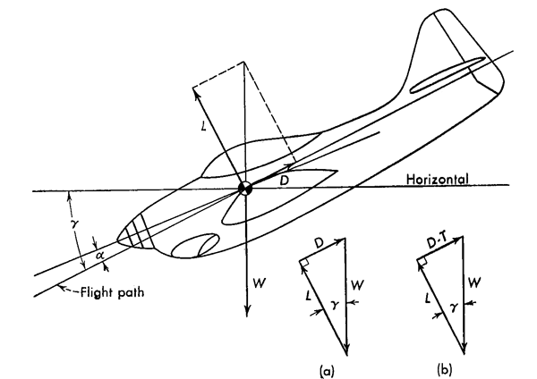
Forces in the steady glide, from Connolly, Figure 11:8.
Determining the pitch change on approach for increases in airspeed with a given flap setting seems to be a case of not enough information to have the necessary precision. But since we are only looking for an idea of the magnitude of the change, we can assume the power off glide performance is good enough an approximation. With that taken as read, we can turn to our aerodynamics text books. . .
- For small angles of glide (γ) the horizontal speed is almost the same as the flight-path speed, but as the glide angle increases this approximate identity is no longer valid; specifically, if V = flight-path speed,
- In a hodograph representation, VV is plotted against VH, that is, the vertical axis is V sin γ and the horizontal axis is V cos γ. Thus, if we consider the length of a line drawn from the origin to some point on the hodograph, its length is (from the Pythagorean theorem)
- The angle made by the resultant velocity vector with the horizontal is γ, since
- Consequently, the hodograph representation of gliding flight (or any other type of flight) immediately gives sinking or climbing speed, horizontal speed, flight-path speed, and flight-path angle.
VH = horizontal speed = V cos γ
VV = vertical speed = V sin γ
Source: Connolly ¶11:6, pages 313 - 314
Example
(130 KTAS approach speed, 700 fpm vertical velocity, ½° deck angle)
You can determine an airplane's flight path angle given its approach speed and vertical velocity. In the case of a Challenger 604, a typical approach speed may be 130 KTAS with a glide path vertical velocity of 700 fpm.
Of course this precisely matches what we would expect on final approach. Therefore, a Challenger 604 flown on speed with a ½° deck angle will fly a 3.04° flight path. We can use this formula to apply approach speed additives to estimate a resulting deck angle:
| Approach Speed | KTAS | Approach Angle | Deck Angle |
| VAPP | 130 | 3.0 | +0.5 |
| VAPP + 20 | 150 | 2.6 | +0.1 |
| VAPP + 40 | 170 | 2.3 | -0.2 |
From this we can conclude that carrying an extra 40 knots of speed on approach in a Challenger 604 might result in a nose-first landing if the pilot does not flare. We can also conclude that an aircraft with a conventional +5° approach deck angle should not have a problem under the same conditions.
2
Circling approach radius
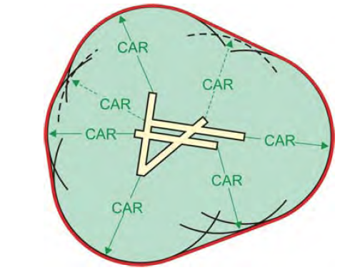
Circling Approach Obstacle Evaluation Area, from TERPS, ¶260, Figure 15-1.
Calculate the Circling Approach Radius (CAR) based on true airspeed, bank angle, and straight segment length using the following formula (radian calculations):
Where:
VKTAS = true airspeed
bankangle = bank angle (from table 4)
S = straight segment (from table 4)
Source: TERPS, Volume 1, §6, ¶260
VKTAS is figured from a flawed formula which converts VKIAS to VKTAS with a substantial error on the high side, i.e., it makes the true airspeed higher than it really is. Of course one could argue this is a good thing, since it widens our circling approach radius. The formula and table 4 appear below, Indicated to True Airspeed.
Using the limiting category speeds for Category C and D at 1,000' and 5,000' MSL, we see:
- Category C, 140 KIAS, 1000' MSL, CAR = 2.83 nm
- Category C, 140 KIAS, 5000' MSL, CAR = 3.09 nm
- Category D, 165 KIAS, 1000' MSL, CAR = 3.70 nm
- Category D, 165 KIAS, 5000' MSL, CAR = 4.05 nm
Each of these areas far exceed the 1.7 nm (Cat C) and 2.3 nm (Cat D) radii we have been trained to use. What bank angle is required to properly fly these radii?
- Even rolling out at the ridiculous 0.5 nm outlined by current TERPS criteria, a Category C aircraft would need 36° of bank to keep within 1.7 nm at 140 KIAS and 1,000' MSL.
- Rolling out at the equally ridiculous 0.6 nm outlined by current TERPS criteria, a Category D aircraft would need 34° of bank to keep within 2.3 nm at 165 KIAS and 1,000' MSL.
3
Circling turn radius
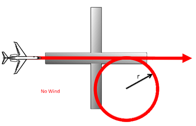
Circling Turn Radius
where:
r = turn radius, ft
V = velocity, knots (TAS)
θ = bank angle, degrees
More about this: Turn Performance.
Doing the math for a few typical TAS while circling:
- At 140 KTAS, 25° bank, turn radius = 0.61 nm
- At 165 KTAS, 25° bank, turn radius = 0.85 nm

Turn radius at 25° bank (nautical miles) = (nautical miles per minute)2 / 9
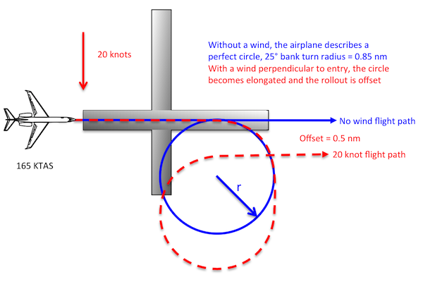
The impact of wind on circling turn radius
We can estimate the impact of wind if we consider the entire air mass moving, with the airplane, in relation to the runway. In that way, we need only consider the amount of time the aircraft takes to complete the circle and compute the speed of the air mass For example, let's say our Category D aircraft is approaching Runway 09 (which faces 090° Magnetic) doing 165 KTAS and that the wind is from the north 360 Magnetic at 20 knots. Where will the aircraft end up after it's 360° turn?
First we need to compute the circumference of the no-wind circle:
Next we compute the time spent in the 360° turn by dividing the distance by the velocity:
Now we can compute how far the air mass, and everything in it, has moved for the duration of the turn to compute the aircraft's offset from the runway when it rolls out:
If you do the math you will find that at 120 KTAS the offset is around 1/50th of the crosswind, at 140 KTAS the offset is around 1/40th of the crosswind, and at 150 KTAS the offset is around 1/30th of the crosswind. Is that important? No, not at all. What is important to know is that when circling it is not uncommon to be turning away from the wind before aligning with the landing runway and this will blow you further away from the runway by a half mile or more. You should be aware that staying within the old TERPS circling approach area may be next to impossible with a wind like this.
4
Crosswinds
Crosswind chart example
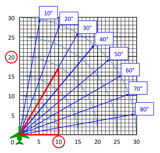
Just as the sine of 30° = 0.5, the cosine of 60° = 0.5. You can also figure that the sine of 60 or the cosine of 30° is √3 / 2 = 0.87, almost 90 percent. The cosine or sine of 45° is 1 / √2 = 0.71, almost three-fourths. That leads to a few handy rules of thumb when it comes to crosswinds:
More about this: Crosswinds.
A thirty degree crosswind is equal to one-half the full wind factor.
A forty-five degree crosswind is equal to three-fourths the full wind factor.
A sixty degree crosswind is equal to ninety percent of the full wind factor.
5
Indicated Air Speed (IAS) to True Air Speed (TAS)
One of the gotchas (of many) in circling approaches is that your true airspeed increases your turn radius and that could leave you outside the computed Circling Approach Radius (CAR). . .
Where circling is authorized, evaluate the circling approach area for each CAT published on the procedure. The Circling Minimum Descent Altitude (CMDA) is based on the results of the circling area evaluation and the evaluation of the final segment delivering the aircraft to the circling area. Also see Vol. 1, chapter 3, paragraph 3.2.1b.
- Obstacle Evaluation Area (OEA). The area for each CAT is based on true airspeed (VKTAS). The minimum altitude used for true airspeed conversion is 1,000 ft above airport elevation.
Use the following formula for converting indicated airspeed (VKIAS) to true airspeed (VKTAS) is:
Where:
VKIAS = indicated airspeed (from table 4)
alt = airport elevation (MSL)
k = height above airport (1,000 ft minimum)
| CAT V | KIAS | Bankangle | Straight Segment Length (S) |
| A | 90 | 25 | 0.4 |
| B | 120 | 25 | 0.4 |
| C | 140 | 20 | 0.5 |
| D | 165 | 20 | 0.6 |
| E | 200 | 22 | 0.7 |
Table 4: Circling Approach Area Parameters, from TERPS, ¶260, Table 4.
That is quite a formula, but is it accurate?
- At 1,000' MSL, 140 KIAS = 146 KTAS
- At 5,000' MSL, 140 KIAS = 155 KTAS
- At 1,000' MSL, 165 KIAS = 172 KTAS
- At 5,000' MSL, 165 KIAS = 182 KTAS
Source: TERPS, Volume 1, §6, ¶260
The TERPS formula appears to be at odds with the classical definition which says
TAS = EAS ( 1 / √(σ).
More about this: ICE-T. EAS is essentially equal to IAS at low altitudes and speeds and reveals:
- At 1,000' MSL, 140 KIAS = 142 KTAS
- At 5,000' MSL, 140 KIAS = 151 KTAS
- At 1,000' MSL, 165 KIAS = 167 KTAS
- At 5,000' MSL, 165 KIAS = 178 KTAS
These numbers agree with what you would find on a typical flight computer.
More about this: CR-3 / CPU-26 Exercises. For low altitudes you might also consider this gem from the past:
At low altitudes you can approximate KTAS by doubling your altitude in thousands of feet and adding to your KIAS.
The TERPS formula for converting KIAS to KTAS appears to err on the high side, which might be a good thing for estimating circling approach areas but is not very useful for other tasks.
6
Top of Descent (TOD)
Top of descent angle
Back in the days where we didn't get so many "slam dunk" arrivals you could pretty much guarantee a smooth descent if you started down at a distance equal to three times your altitude (in thousands of feet). So, for example, if you were at 30,000 feet, start down at 3 x 30 = 90 nautical miles. If you wanted to get fancy, you could subtract your field elevation, so an arrival to Denver would be started at 3 x (30 - 6) = 72 nautical miles. You can use a little trigonometry and find out this comes to a perfect 3° descent angle.
More about this: Trigonometry for Pilots.
In one of my VIP squadrons we tried to be even more gentle and would use 4 times our altitude in thousands. So we would start down even earlier in our example: 4 x 30 = 120 nautical miles. That comes to a 2.5° descent angle.
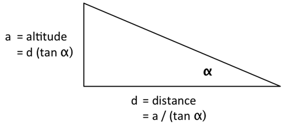
The three times and four times rules can be proven as pretty close to fact using the relationship a = d (tan α), where a is the altitude, d is the distance, and α is the angle. You just need to be careful about the units, converting feet to nautical miles: 1 nm = 6,076'
| α | tan( α ) | 1000' / tan( α ) | ÷ 6076 |
| 3° | 0.0524 | 19,081' | 3.1 nm |
| 2.5° | 0.0437 | 22,904' | 3.8 nm |
If you want a 3° descent, start down at 3 times the altitude to lose in thousands of feet.
If you want a 2.5° descent, start down at 4 times the altitude to lose in thousands of feet.
But you are based in the Northeast you say, and air traffic control doesn't allow you to do anything for your convenience. You are going to be told when to start down and that's all there is to it. Well, you can compute your own descent angle using the tangent relationship just shown. Fortunately, it only involves division:
More about this: 60 to 1.
7
Turn radius
turn radius
where:
r = turn radius, ft
V = velocity, knots (TAS)
θ = bank angle, degrees
The horizontal component of lift will equal the centrifugal force of steady, turning flight. This fact allows development of the following relationships of turning performance:
Source: ATCM 51-3, pg. 178
Doing the math for a 25° bank turn and converting V (in knots) to v (in nautical miles per minute) you get a good approximation:
Turn radius (nautical miles) = (nautical miles per minute)2 / 9
More about this: Turn Performance.
8
Vertical Navigation (VNAV) on approach
AGL vs. DME to go
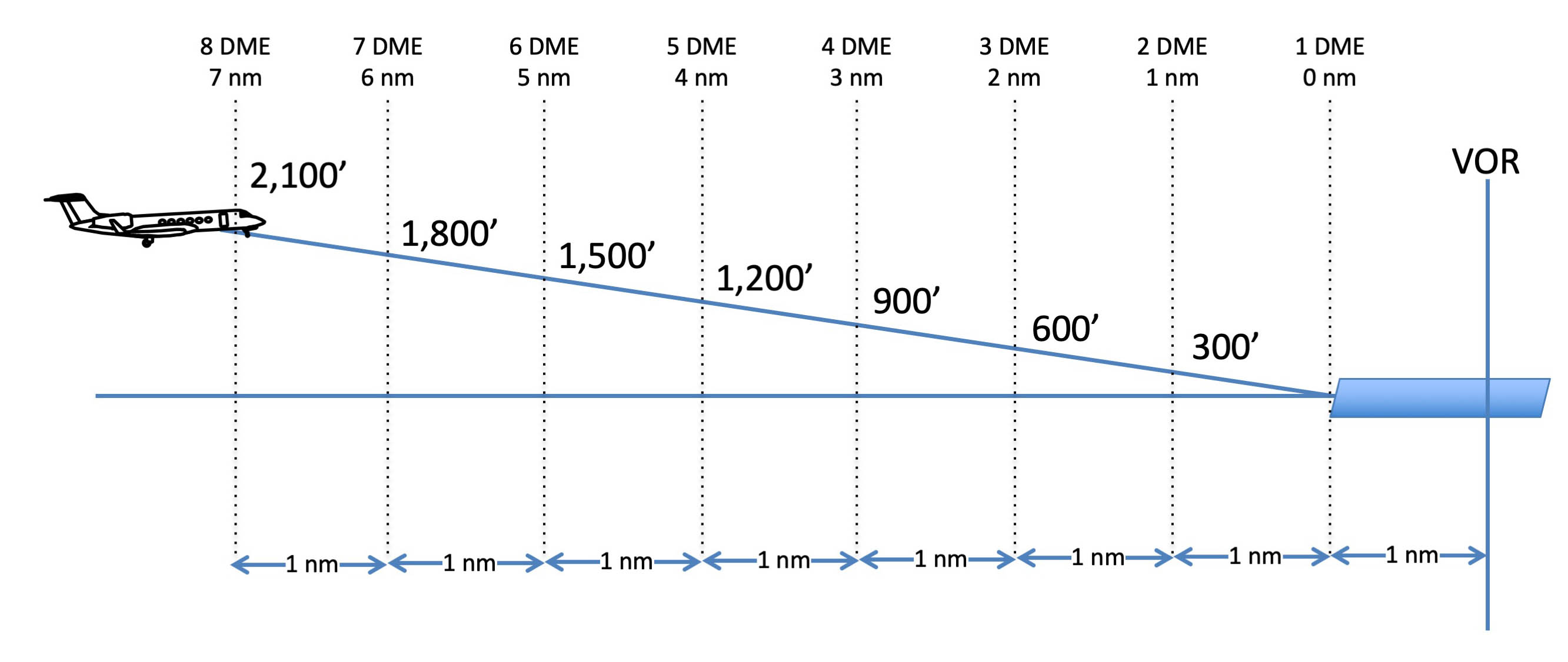
We often use 300 feet per nautical mile as a wag for how high we should be on final approach. It is pretty close to a three degree glide path, convenient eh?
It is more than convenience, it is trigonometry. The real number, as it turns out, is 318 feet per nautical mile:
A 3° glide path requires 318 feet per nautical mile, or about 300 feet a mile.
More about this: Landing and Approach VVI.
9
Wing tip hit bank angle on landing
Aircraft with wide wing spans are rarely permitted to land using a sideslip (also known as the "wing low" technique) because doing so could catch the wing tip. For more about this, see Crosswind Landing. Very few manufacturers volunteer how much bank angle you need to ding a wing tip on landing, but you should be able to figure it out. Here is a GV example.
GV bank angle to hit a wing tip in a 3-point attitude
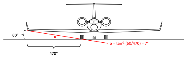
In the G450 the math comes to α = tan-1 (60/382) = 9°
The GV Maintenance Manual (§6) says the wing tip is 60" off the ground and 560" from the center of the aircraft. Of course the height varies with strut pressure and loading above BOW, but we can use this for the sake of argument. It also notes the main landing gear are 90" from the center of the aircraft. With this information we know that a bank of 7° will cause the wing tip to contact the runway just as the wheel touches ground. But there is more to the story because the wings are swept.
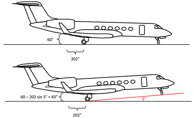
GV wing tip clearance in a 3-point attitude versus 5 nose up
In the G450 the math comes to 60 - 199 sin 5° = 43"
The GV Maintenance Manual (§6) also gives us the fuselage station of the main landing gear tires (from FS 576 to FS 632, for a center point of FS 604). The aft part of the wing tip is at FS 806, so the wing tip is 202" behind the main landing gear tires.
In a 3-point attitude, as we've already discussed, the wing tip is 60" off the ground. In a normal no-flare touchdown, the nose will be 3.3° high, based on a 2006 Gulfstream study on Eye Wheel Height. If we assume the flare raises the nose another 2°, the wing tip will be lowered 15".
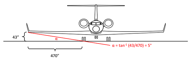
GV bank angle to hit a wing tip in the landing attitude
In the G450 the math comes to α = tan-1 (43/382) = 6°
The result is we see it will only take 5° of bank to get the wing tip in a normal flare. Note that any kind of yaw into the low wing will get the wing tip even sooner.
References
(Source material)
Air Training Command Manual 51-3, Aerodynamics for Pilots, 15 November 1963
Connolly, Thomas F., Dommasch, Daniel 0., and Sheryby, Sydney S., Airplane Aerodynamics, Pitman Publishing Corporation, New York, NY, 1951.
Gulfstream Eye Wheel Height Paper, GIVX-HF-06-01-11.
Gulfstream GV Maintenance Manual, Revision 25, August 31, 2005
United States Standard for Terminal Instrument Procedures (TERPS), Federal Aviation Administration 8260.3B CHG 25, 03/09/2012
Please note: Gulfstream Aerospace Corporation has no affiliation or connection whatsoever with this website, and Gulfstream does not review, endorse, or approve any of the content included on the site. As a result, Gulfstream is not responsible or liable for your use of any materials or information obtained from this site.