If you fly an airplane with balance tabs you should understand the concepts that make them work. You are basically flying a small aerodynamic force using small mechanical pressures that become multiplied by the differences in air pressure.
— James Albright

Updated:
2014-04-28
It was a pretty neat idea from the 1950's that is still being employed by some airplanes today.

1
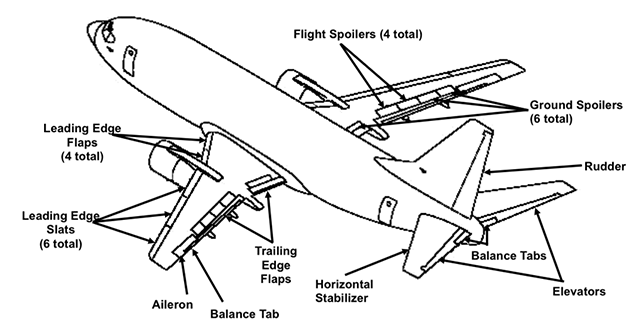
The concept behind balance tabs
a-1_fig_1-33.png)
Figure: Flight control balance tabs, from 1C-135(K)A-1, figure 1-33.
The KC-135A tanker was designed in the early 50's and continues to fly today using most of the technologies available way back when. Each flight control relied on balance tabs, which made for sloppy handling. The explanation in the old KC-135A flight manual, however, remains valid:
Movement of the control surfaces is aided by the pressure balance panels located in the cavity ahead of the surfaces. See [the figure on the top of this page]. This balancing effect is caused by the pressure differential between the upper and lower cavity vents acting upon the area of the balance plate and surface nose overhang. The difference in cavity vent pressure is a result of both control surface deflection and angle of attack and at all times acts to assist control motion. The balance panels have been factory set for proper control travel and feel characteristics.
Source: 1C-135(K)A-1, page 1-48.
2
Modern aircraft balance tabs
B-737 Flight controls, source unknown.
I've not seen balance tabs on an airplane since the Boeing 707s I flew in 1985. Reading mishap reports, however, I see the Boeing 737 still uses them. What follows comes from an accident investigation resulting from improper adjustment of a Boeing 737's elevator balance tabs.
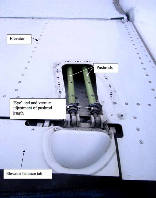
Boeing 737 elevator tab pushrods, from AAIB, G-EZJK, figure 10.
The B737-700 is fitted with tabs on the trailing edges of the elevator control surfaces. These act as balance tabs to reduce the control forces required to move the elevators and are critical for manual control of the aircraft in the event of a double hydraulic system failure. Two control rods link each tab to the elevator control system such that when the elevators are deflected the tabs also deflect. The position of the tab relative to the elevator is controlled by the length of the rods. Coarse adjustments to the pushrod length are made by rotating the ‘eye’ end of the pushrods, fine adjustments are made by rotating a vernier fitting (see [the Figure]).
Source: AAIB, G-EZJK, pg. 18.
References
(Source material)
Air Accidents Investigation Branch, Serious Incident, Boeing 737-73V G-EZJK, 9/2010.
Technical Order 1C-135(K)A-1, KC-135A Flight Manual, USAF Series, 25 April 1957