Radar was invented by the militaries of the world leading up to World War II as a method of detecting and determining direction and range to an enemy. The term RADAR was coined by the United States Navy: Radio Detection And Ranging. A scientist at M.I.T., working for the United States Air Force, came up with a way to use radar to detect weather. Interesting? Maybe not, but it is a good introduction to understanding how weather radar works.
— James Albright

Updated:
2022-06-08
Various manufacturers have manuals and training courses that you may or may not have access to; using the radar in your aircraft seems to be "assumed knowledge." They assume you know how to use it. The basics here should get you started.
3 — Amplitude of target's return
If you want to get more technical, checkout Andreas' article at Engineering Pilot: Weather radar evolution: from tilt management to GNSS interference.

1
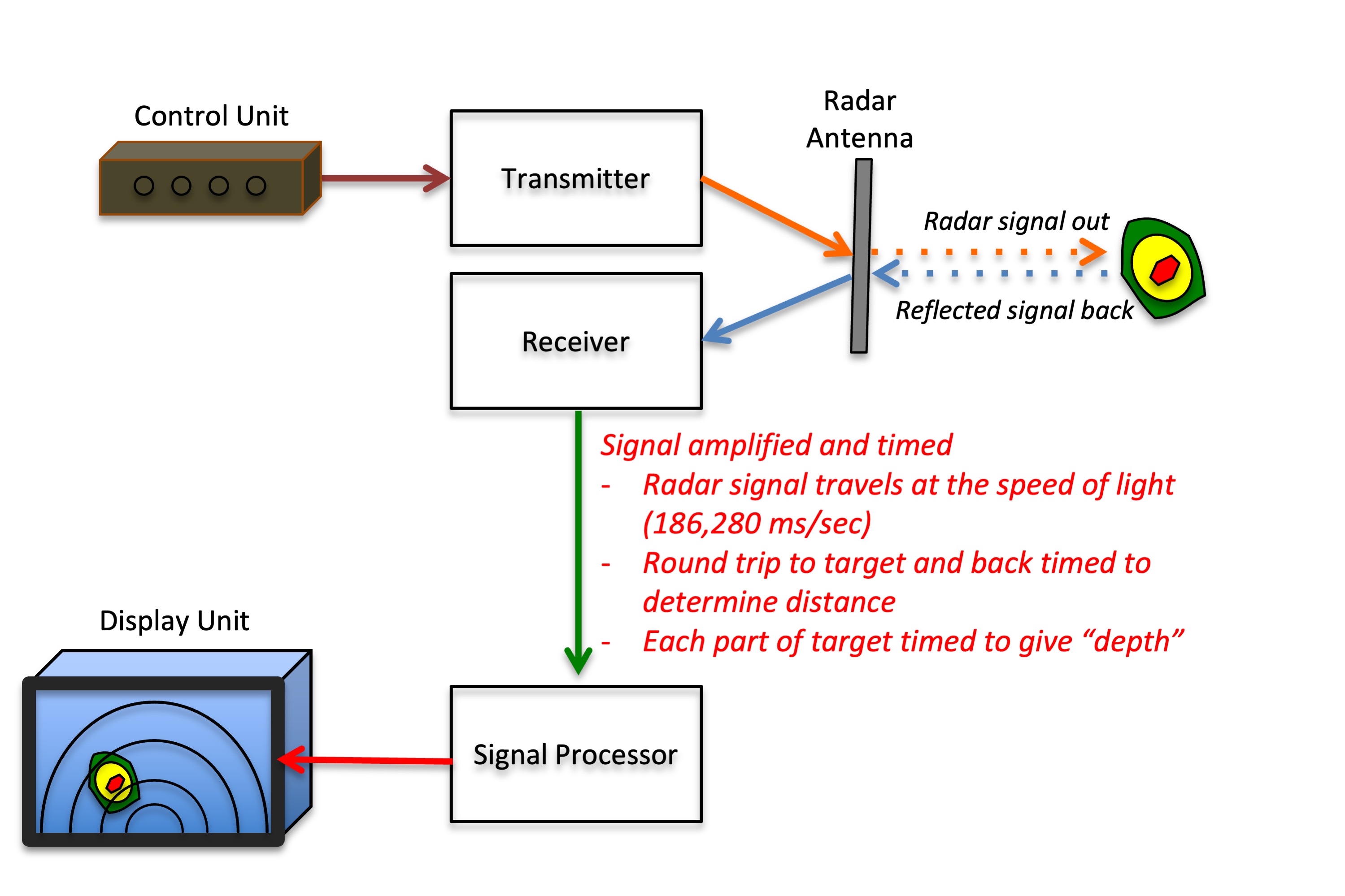
Distance to target
Radar beams are nothing more than radio waves broadcast from your radar antenna in a narrow beam at a certain speed. The speed is said to be the speed of light, but perhaps a little less. The electrons bounce off your "target" and come back. The radar does a little math (distance equals speed multiplied by the time) to figure the distance.
Distance to target
2
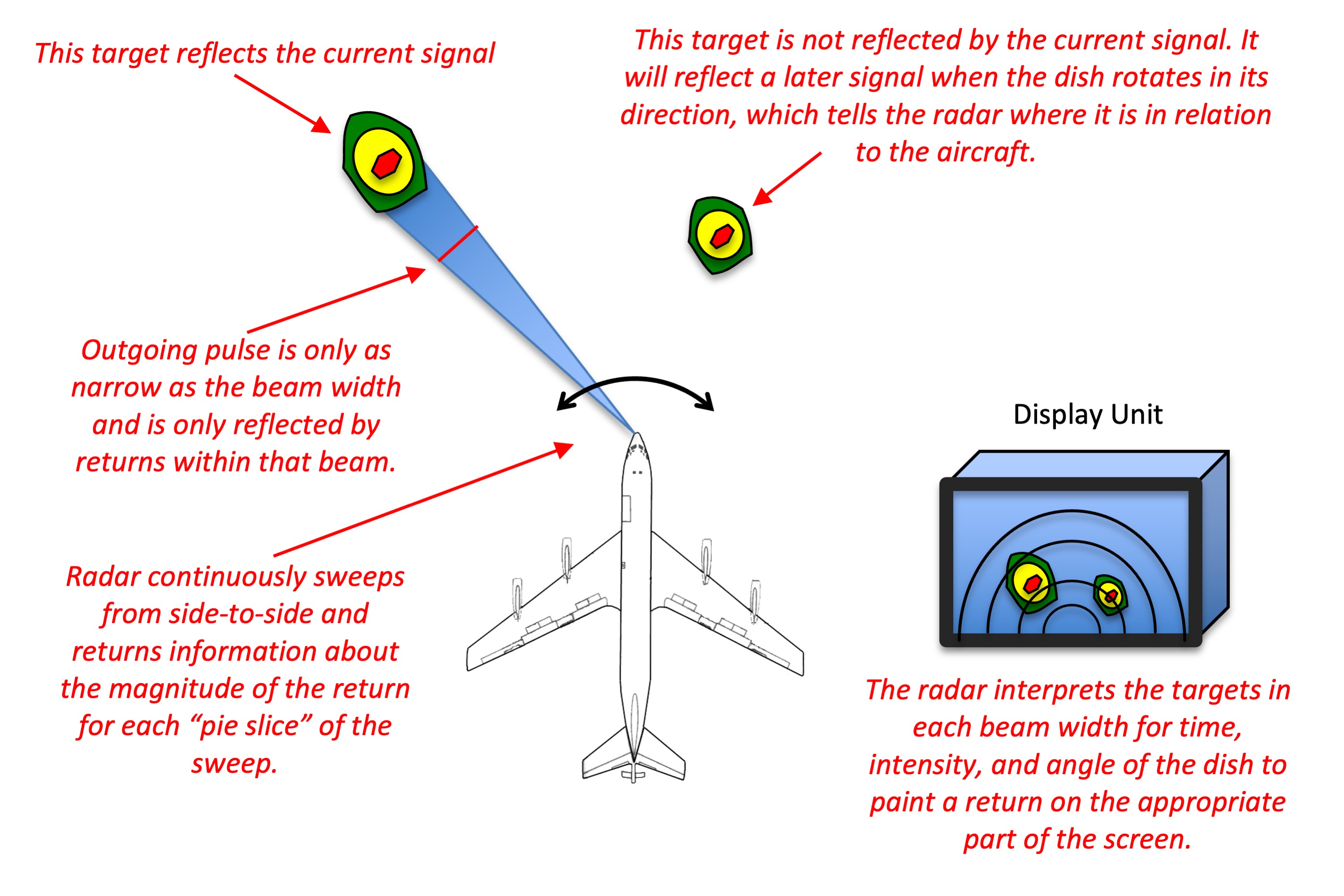
Direction to target
The radar beam is sent off in a narrow direction which can be aimed, either by mechanically or electronically steering the antenna. The radar simply translates the direction off your antenna versus the longitudinal axis of the aircraft to display the correct relative direction.
Direction to target
3
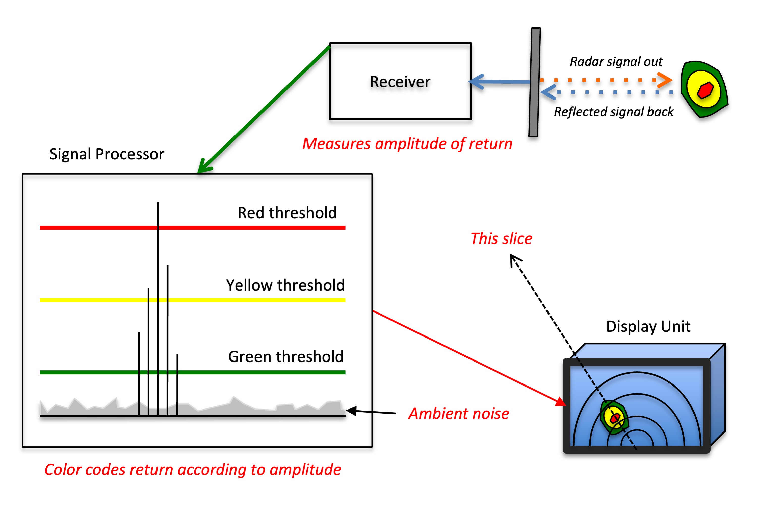
Amplitude of target's return
The radar signal processor evaluates each return for intensity and round trip time. The data is then converted to distance and intensity. Varying intensities are color coded.
4
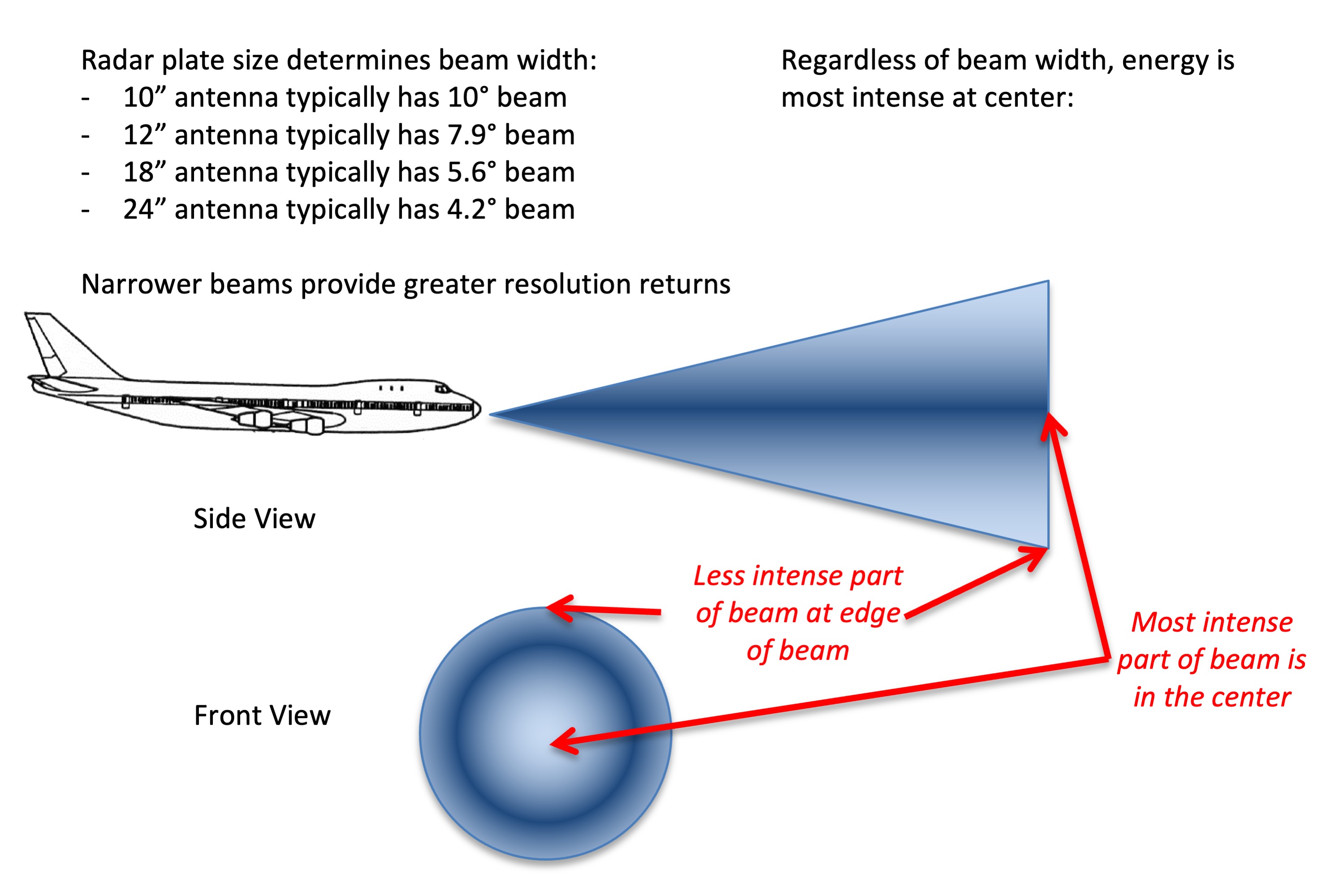
Beam width focus
Beam width focus
You can think of the radar beam to be something like the beam of a flashlight: it is more intense at the center and the amount of light shone decreases the further away you get from the center. In the case of radar, the larger the antenna the more narrow the radar beam is. This increases the amount of energy at the center. You can have a stronger radar beam, or you can extract more information with less power.
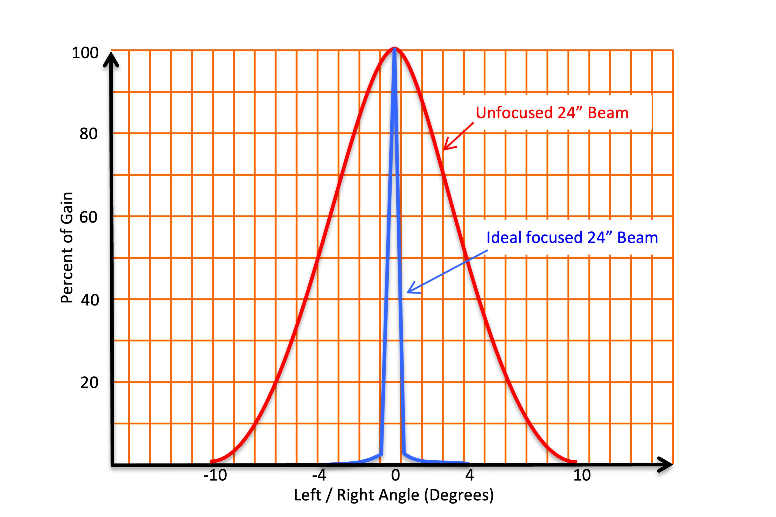
Beam width and gain
5
Reflection and attenuation
If the beam is aimed to the most intense part of the storm and the gain left in “calibrated” mode, the colors should provide useful storm information. Each target lessens the signal strength (attenuation). If the signal is attenuated to zero, a shadow results, possibly hiding more weather.
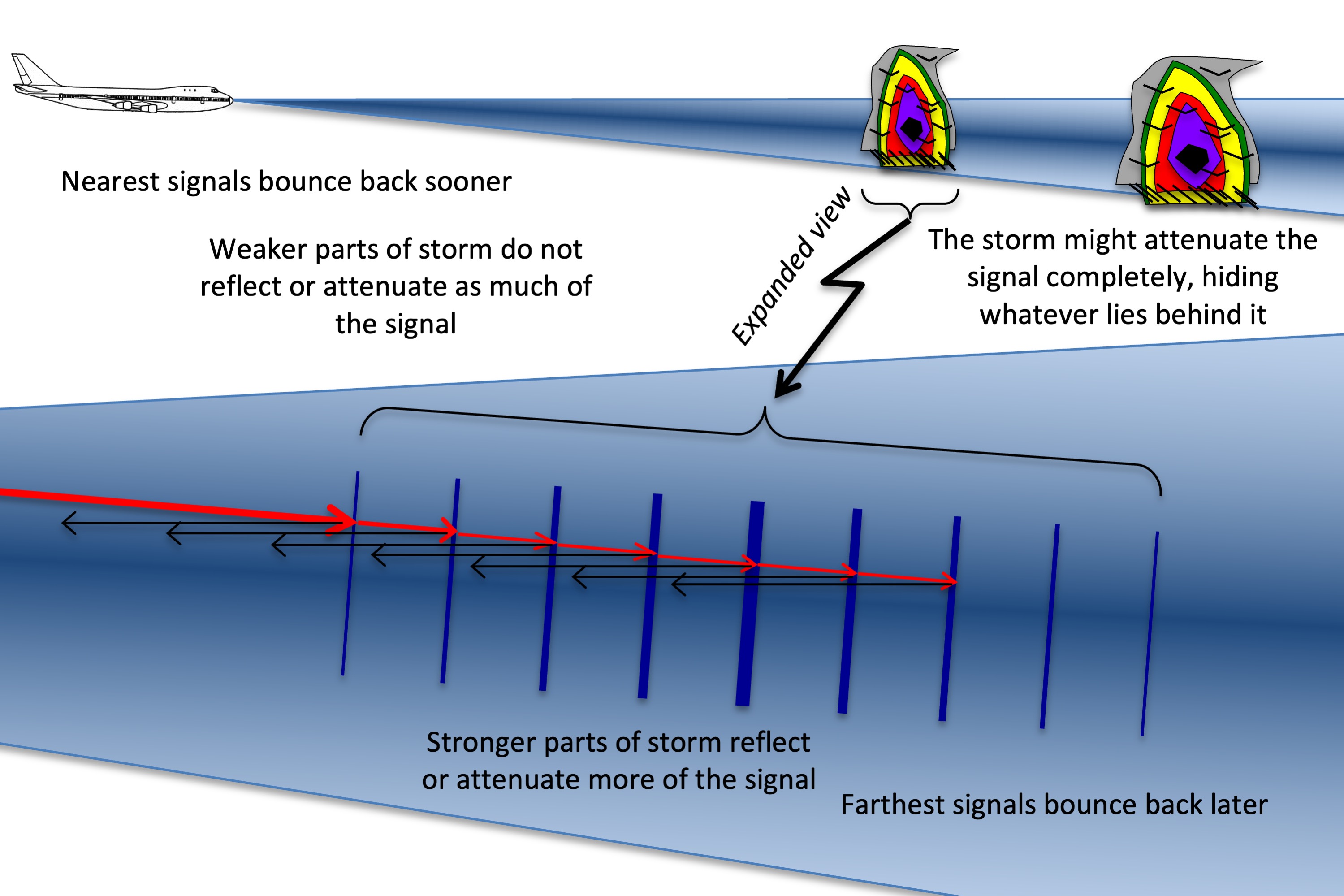
Reflection and attenuation
6
Tilt
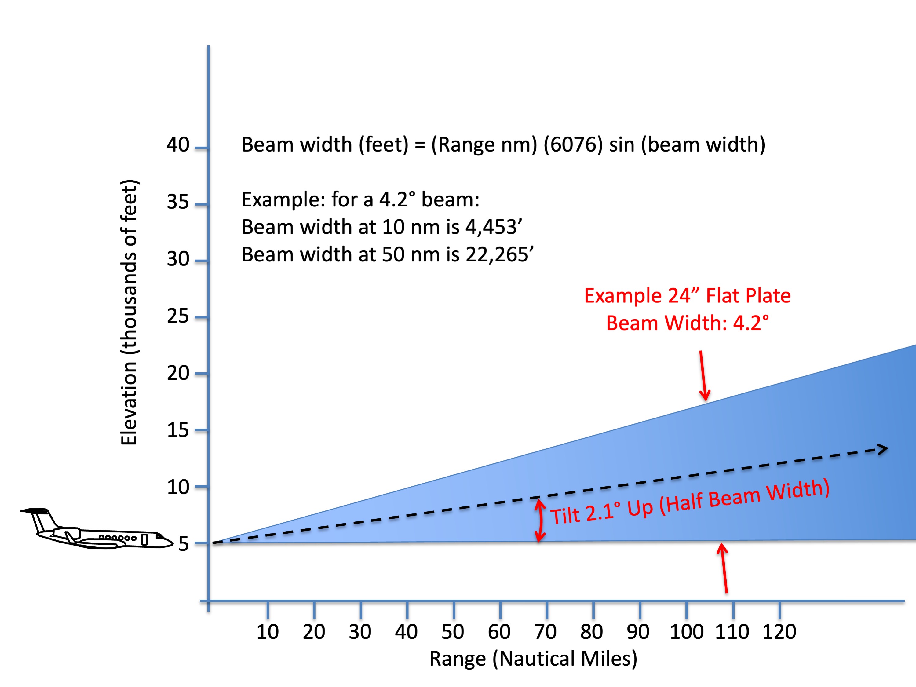
The radar paints more than just a point at the end of the beam, it includes everything in the width of the beam. In the case of a 24” radar:
Distance/Beam Width
10 nm / 0.73 nm
50 nm / 3.66 nm
100 nm / 7.33 nm
200 nm / 18.32 nm
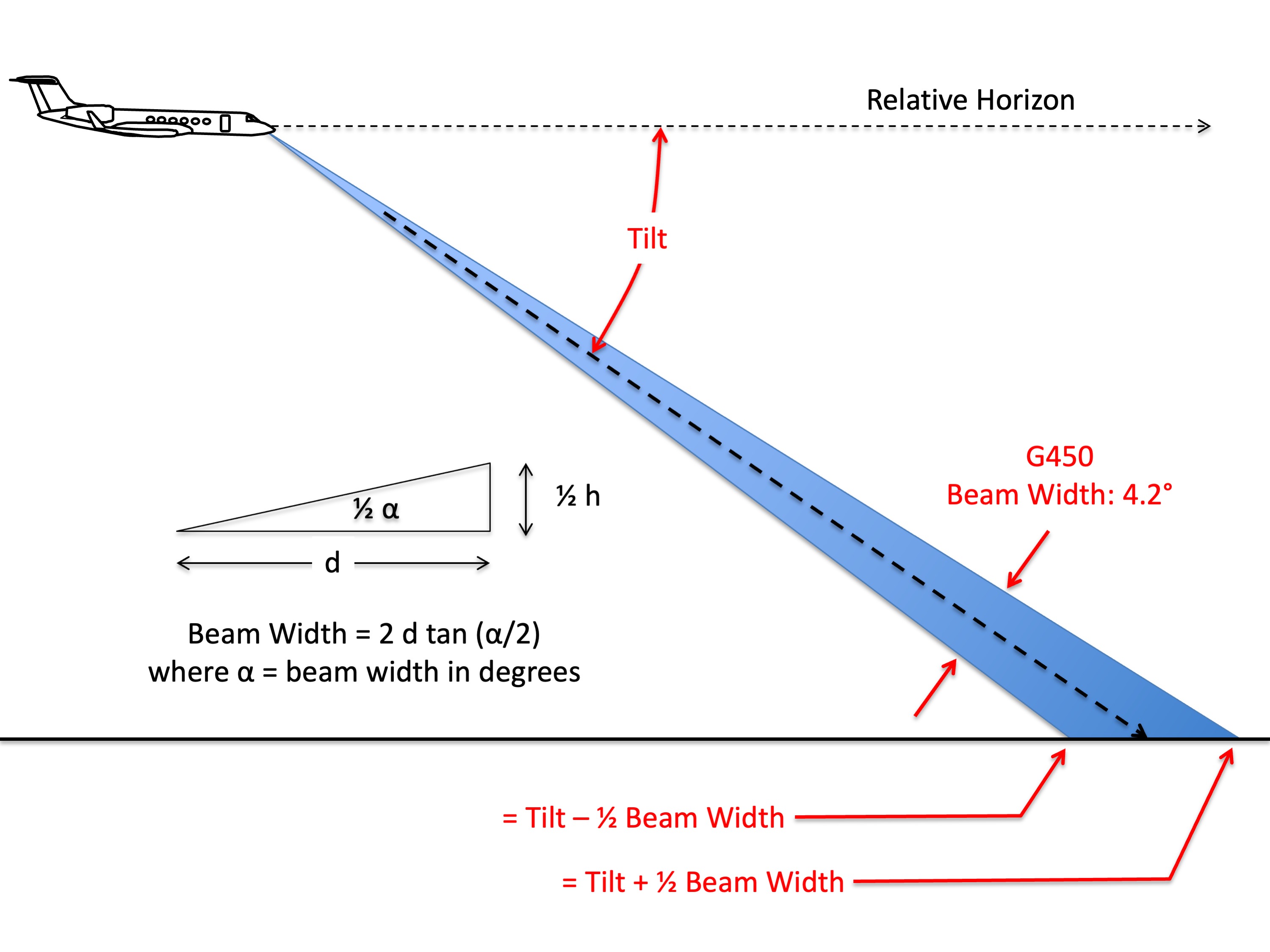
Radar tilt, G450 example
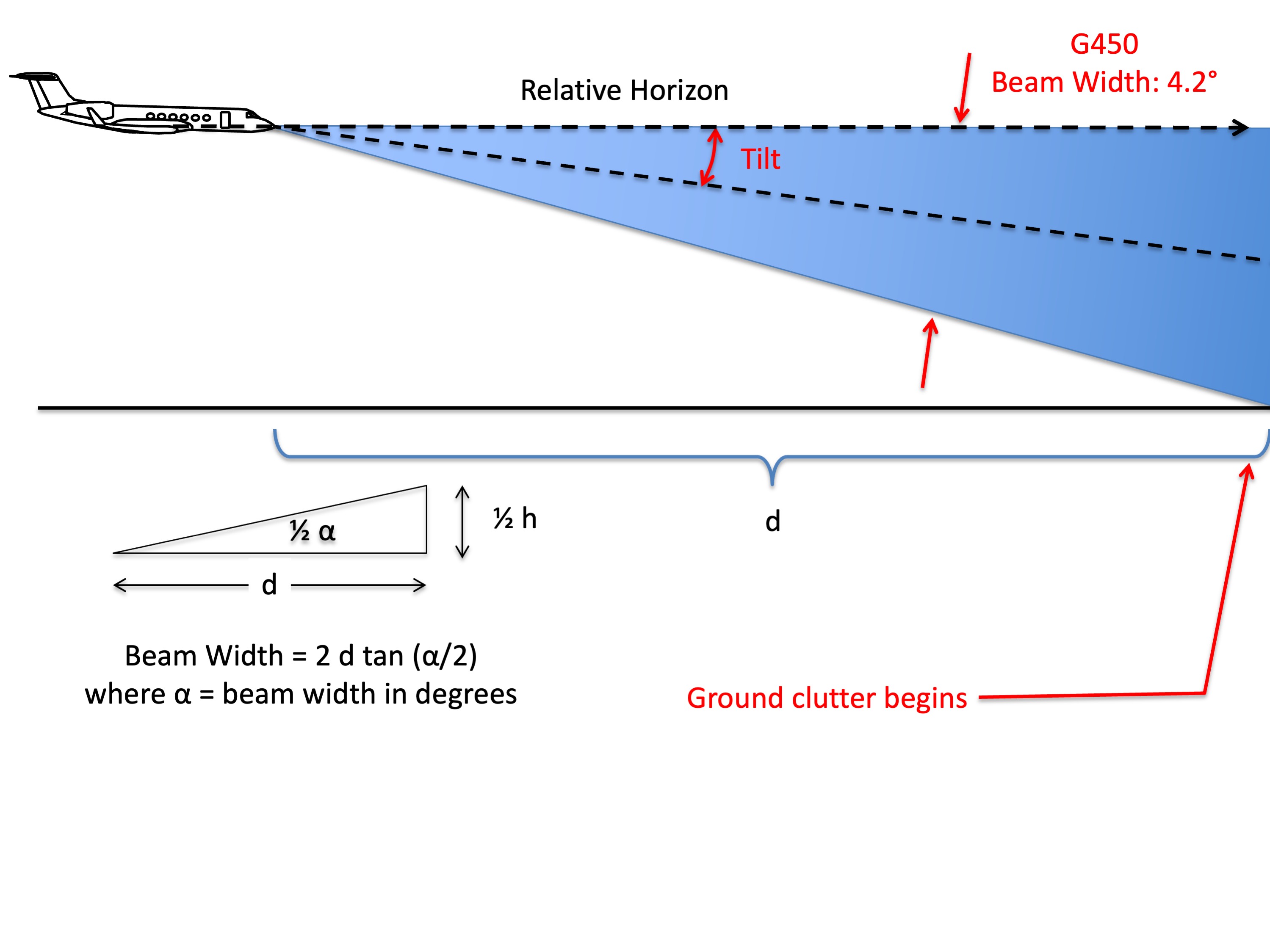
Radar tilt, level flight, G450 example
Radar tilt, low altitude, G450 example
7
Calibration
The colors displayed by most radar are not arbitrary, then tend to come from this standard:
To standardize thunderstorm language between weather radar operators and pilots, the use of Video Integrator Processor (VIP) levels is being promoted. The National Weather Service radar observer is able to objectively determine storm intensity levels with VIP equipment.
1 “weak” and 2 “moderate” — light to moderate turbulence is possible with lightning
3 “strong” and 4 “very strong” — severe turbulence is possible with lightning
5 “intense” — severe turbulence, lightning, hail likely with organized surface gusts
6 “extreme” — severe turbulence, lightning, large hail, extensive surface gusts
Source: Advisory Circular 00-24B, Thunderstorms, ¶6.
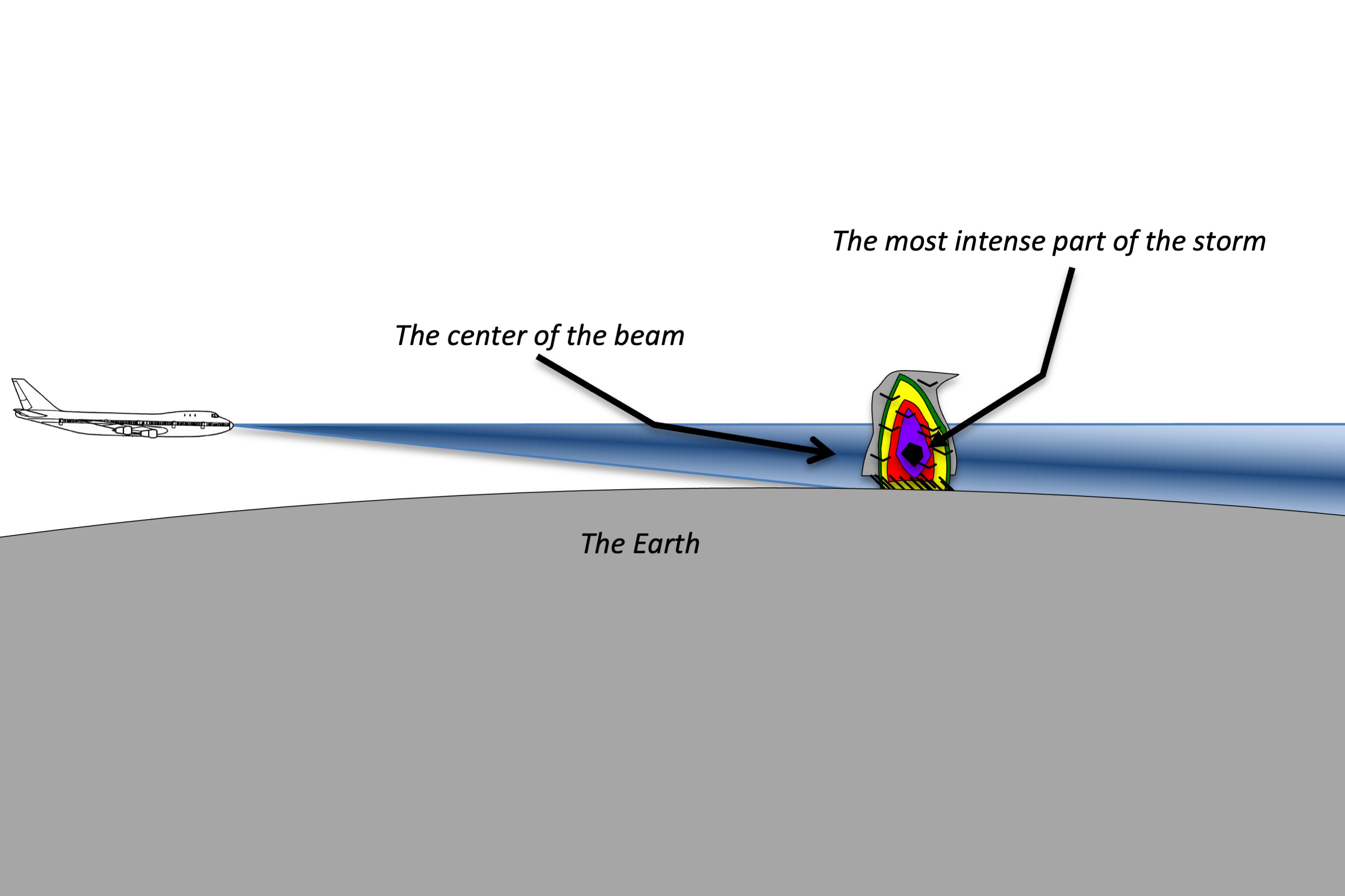
Radar beam aimed for most intensive part of thunderstorm
Radar calibration
Most modern radar manufacturers have adopted these levels with a color code. With the radar set to a preset gain, you can expect the following:

Radar levels
Most modern aircraft radars have calibrated gain settings that ensure the colors you see on the radar display reflect standard intensity levels. On some the setting is noted as “AUTO” and still others may default to calibrated settings and allow the pilot to switch to “Variable.” It is vitally important to leave the gain in its “Preset” position. There is only one exception, and that is when looking for radar shadows. (Next section.)
8
Radar shadow technique
The technique
The best way to detect a thunderstorm is to aim the tilt down far enough to paint lots of ground clutter and then look for returns. The entire beam needs to fall into the weather. A large return with no shadow can be a city, a lake, a tall mountain, or a thunderstorm. Compare the map of the return to the map of the terrain.
The photo shown is headed east to Boston. Notice the ground clutter disappears behind the large thunderstorm.
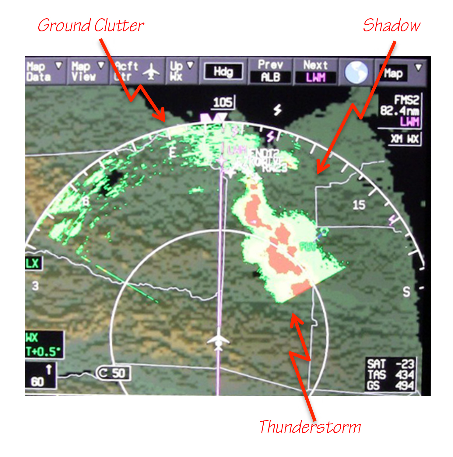
Example of radar shadows flying into Bedford, MA (KBED)
Here is how that looked from the cockpit:
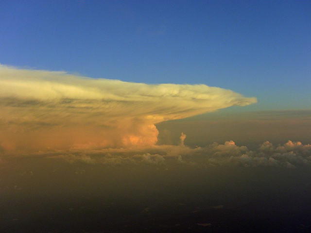
A view from the cockpit
Adjusting gain to look for shadows
Lowering the gain tends to make weather seem less intense than it is, and that can decrease the radar’s ability to “poke” through weather. The result could reveal a shadow:
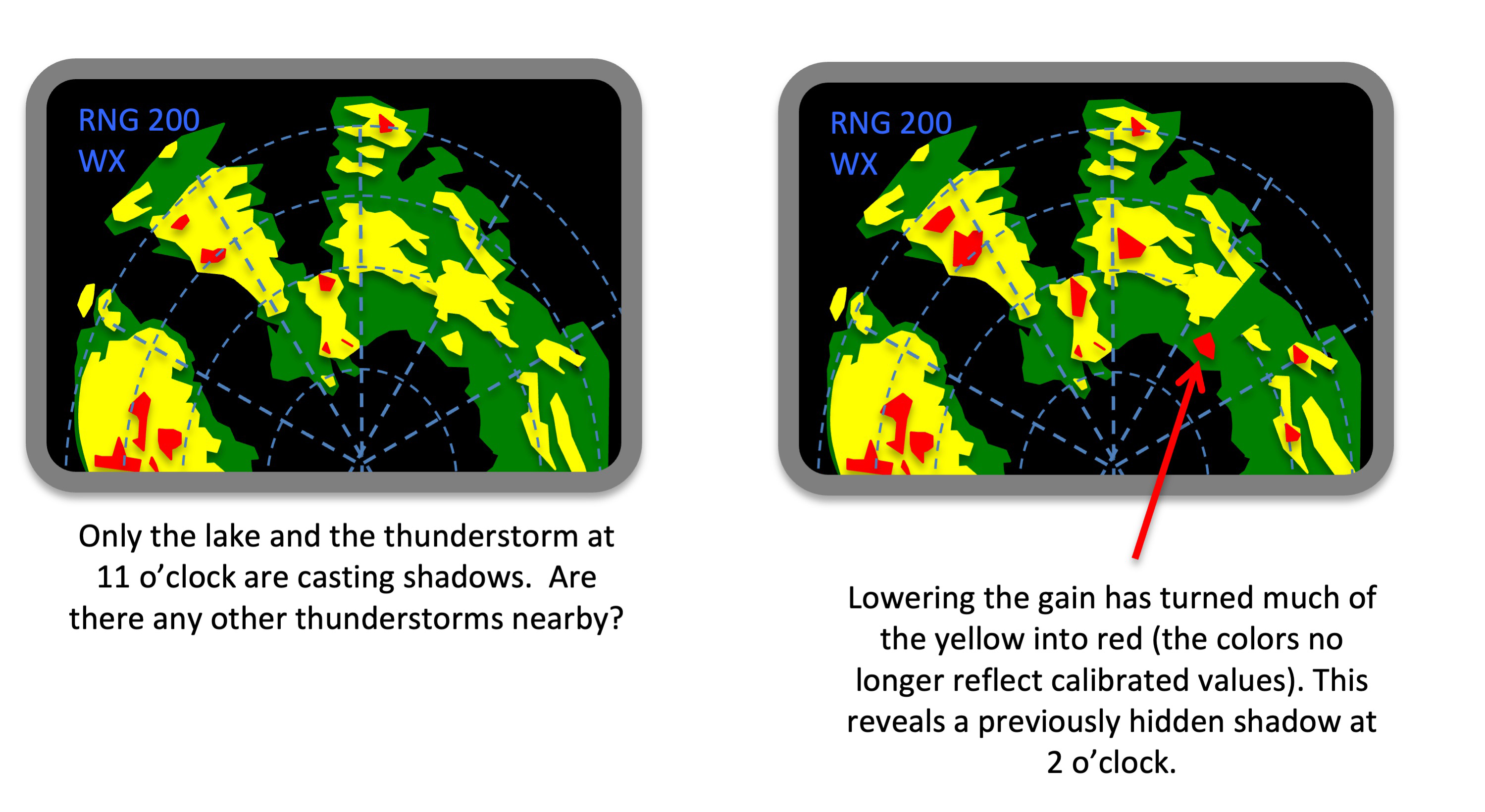
Looking for shadows by adjusting gain
Adjust tilt to look for shadows
Adjust the tilt until you paint the ground or a good portion of the weather. Low hills and cities do not cast shadows. Bodies of water do not reflect radar beams directly and can appear to be shadows, having good situational awareness will detect these. Large thunderstorms cast shadows – that tells you the thunderstorm is real, large, and dangerous. You have no idea what lies behind the thunderstorm in the shadow.
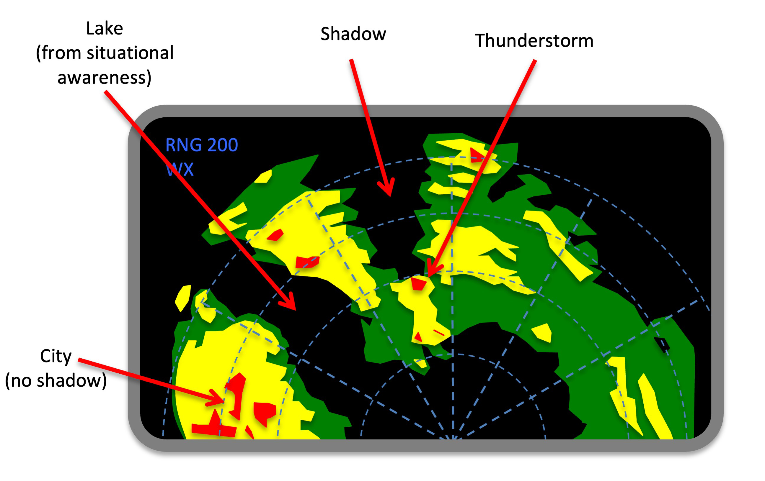
Looking for shadows by adjusting tilt
9
Radar confidence check
The why
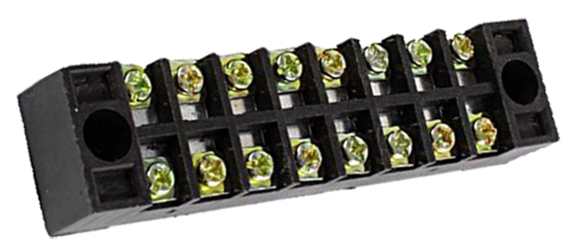
A wiring block connector
Is your radar working? How do you know? Ah, it has a test screen and that says it is working fine. Consider a few examples.
1991
While flying brand new GIII's for the Air Force I was frustrated by the radar's poor performance. The test screen said it was working perfectly but we quite often ran into weather our radar was blind to. Everyone at Gulfstream blamed it on the extra coats of paint we had. A year into my tenure there I was watching a mechanic work under the radome and noticed three missing wires from the R/T unit to the radar dish. We discovered that all ten of our Gulfstreams were missing the wires. We reconnected them and the radars started working brilliantly.
2001
One of our CL-604's seemed to have an on again/off again temper that finally led one of our crews into a hail storm. The test screen said the radar was fine. The next week, I flew the aircraft on a clear day with scattered build ups plainly in sight. The scope was blind to them in spots, turning allowed them to appear in some parts of the screen but not others. Bombardier gave us another test procedure which it passed. It was, they said, flight worthy. In a flight department of eight pilots, all eight refused to fly the aircraft. They pulled the unit and sent it to the manufacturer who found nearly a third of its circuits were burnt out.
2010
Our brand new G450 seemed only able to paint weather on one side. Tech Ops said that was impossible and besides, the test screen showed its pattern on both sides. After whining to anyone willing to listen we found there was indeed a calibration that somehow got skipped when the airplane was delivered.
The how
We learned a long time ago to turn the tilt down where we know the ground will reflect the beam and if we can see the ground, we know the radar is working. But the question is how far down do you turn the tilt and where should you see the ground returns?
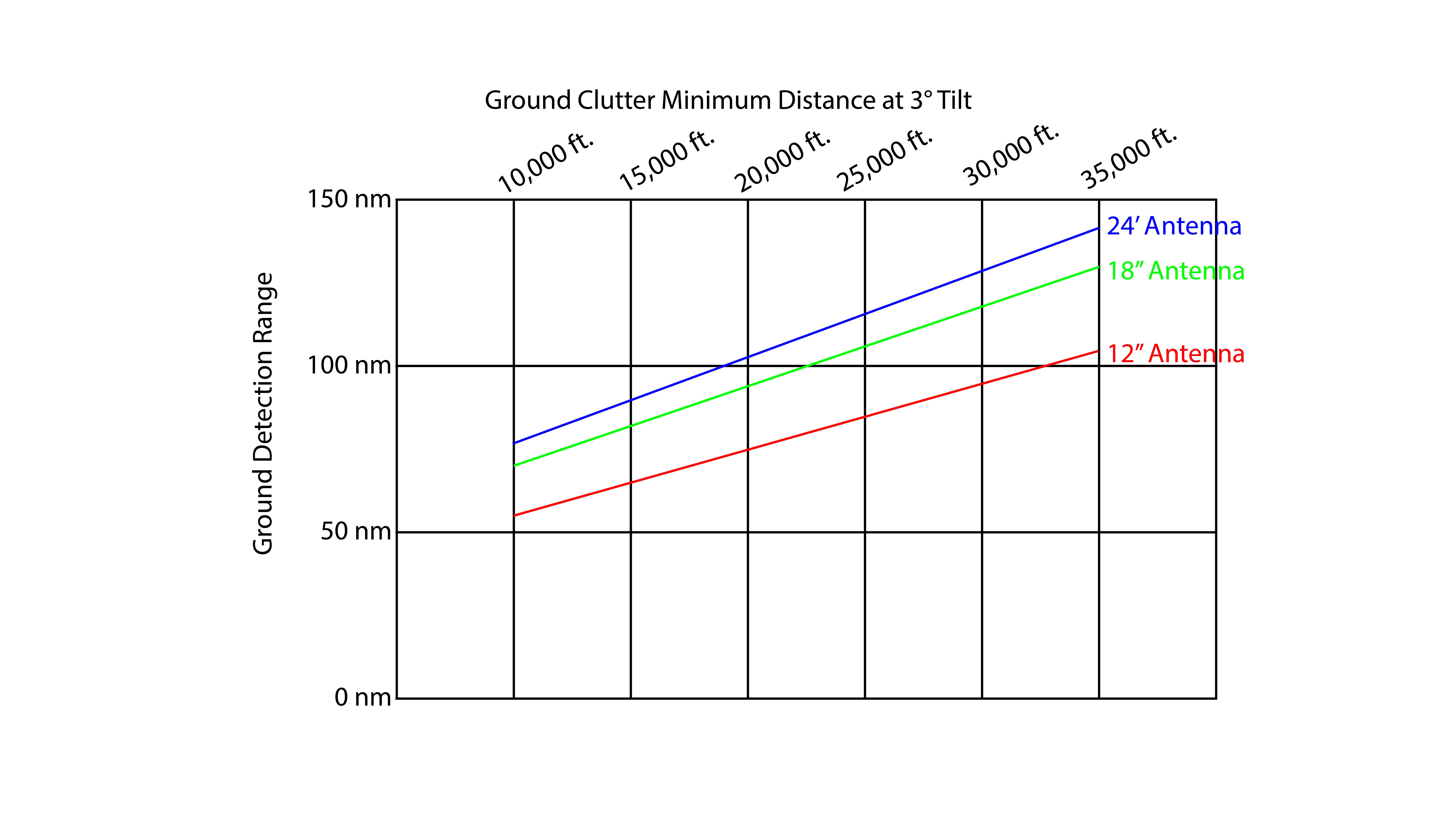
Hypothetical ground clutter ranges at -3° tilt
Honeywell used to produce a chart for their older radars that seemed to work for most radars and I've kept a copy in my notes. This reflects 12, 18, and 24 inch radar plates. The idea is you pick one of the displayed altitudes, turn the tilt to -3°, and look for ground returns at the indicated ranges. I've found this works for all but one type of weather radar, but more on that below.
An example
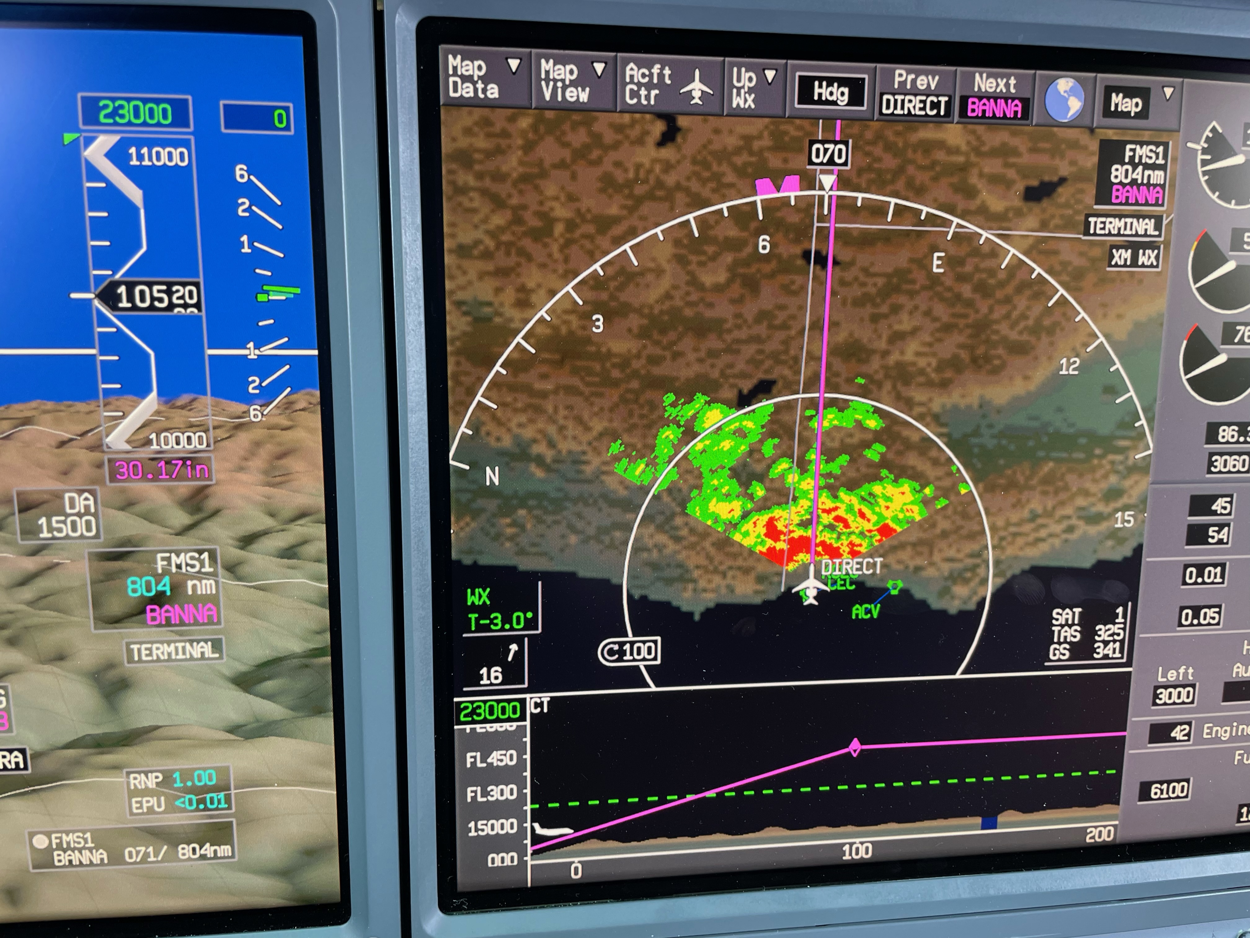
Radar confidence check, G450, at 10,000 feet
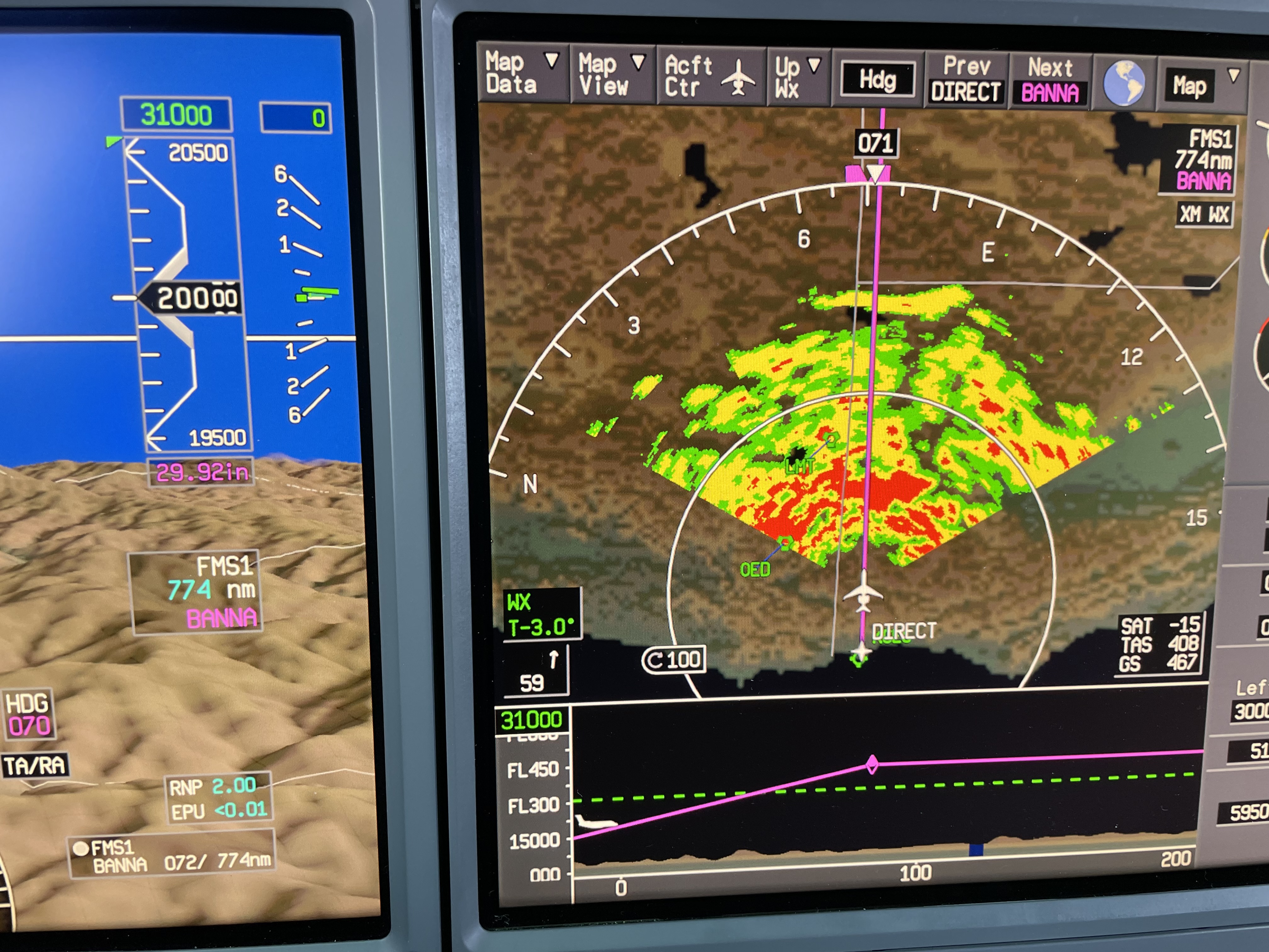
Radar confidence check, G450, at 20,000 feet
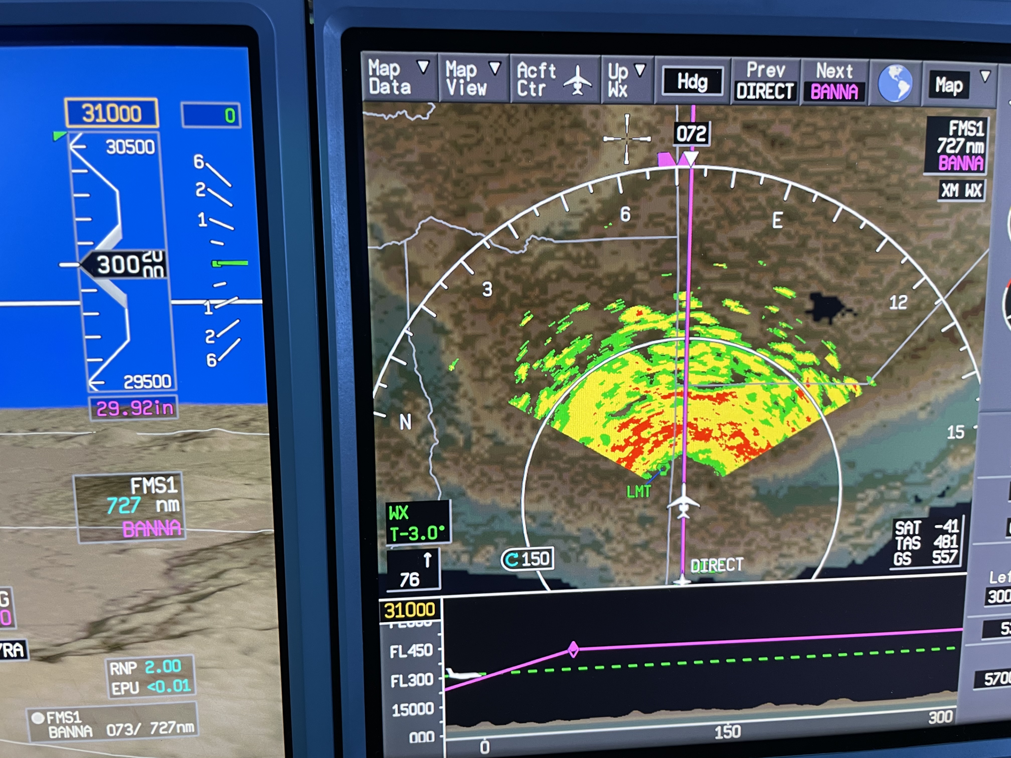
Radar confidence check, G450, at 30,000 feet
The example photos are from a G450 with a 24" radar plate. Of course the distances can be impacted by the terrain and a host of other complications, but the fact the ground return is about where you expect and conforms to the terrain gives you confidence the radar is working.
An exception
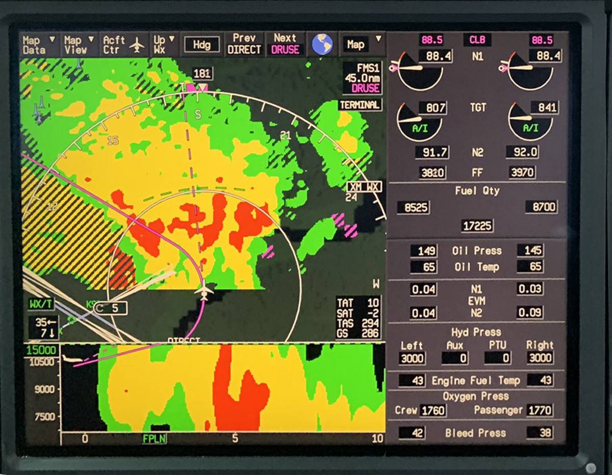
Radar image example, from GVII
Some latest generation radar systems do not have a tilt control and the ability to paint the ground may be limited. In the GVII example shown, the altitude of the image cross section can be changed and the beam can be steered. So if there is something other than ground to paint, you should be able to see it. But I am not aware of an equivalent "confidence level check."