The first description I ever read about Inertial Navigation was meant in jest, but it wasn’t actually too far off: An Inertial Navigation System knows where it is because it knows where it was and where it has gone since.
— James Albright

Updated:
2025-04-22
Before we go any further, one bit of definition is in order. An Inertial Reference System (IRS) is nothing more than something that reports your position (latitude, longitude, geometric altitude), speed, and attitude. An Inertial Navigation System (INS) adds the ability to catalog various positions as waypoints and provides a method of getting from one waypoint to another. If you have an FMS that does this for you, you don't really need an INS, so the IRS is probably what you have installed.
2 — Inertia and Newton’s First Law of Motion
3 — Mechanics of inertial navigation systems
4 — Flight Management Computer (FMC) “Fail Down” sensor logic
5 — Quantum Navigation, a look into the near future?

Wild Bill Kelso navigating, from "1941"

1
Evolution
As I write this, the Global Positioning Satellite (GPS) system is the primary means of navigation for most of aviation. It may be useful to see the evolution of long-range navigation to understand how inertial navigation came to be:
- Pilotage relies on keeping an eye on landmarks and terrain to determine where you are.
- Dead reckoning uses some form of heading information and an estimate of speed to determine where you are going.
- Celestial navigation uses angles between the local horizon and known celestial objects (e.g., sun, moon, or stars), or between those celestial objects to determine position on the earth.
- Radio navigation uses frequency sources from known locations, such as VORs or NDBs.
- Inertial navigation uses a known initial position, attitude, and measured accelerations to determine velocity and the resulting position.
- GPS is a type of radio navigation that uses position and time signals from multiple satellites to determine the receiver’s position.
2
Inertia and Newton’s First Law of Motion
"A body at rest will remain at rest and a body in motion will remain in motion, unless acted upon by an unbalanced force."
Newton’s First Law of Motion implies that bodies have a property called inertia. Inertia may be defined as the property of a body that results in its maintaining its velocity unchanged unless it interacts with an unbalanced force. The measure of inertia is what is technically known as mass. A few points about this first law will make all that follows easier to, well, follow:
- When there are no external forces, objects move with constant velocity.
- Inertia is resistance to changes in motion.
- The amount of inertia an object has is measured by its mass; more mass means more inertia.
So how do we measure those external forces? We first need a stable platform to measure those forces against . . .
3
Mechanics of inertial navigation systems
Gyroscopes
Gyroscope operation,
from Wikimedia
The word gyroscope comes from the Greek gyros, which means circle. In a conventional gyroscope, the gyro is a spinning wheel mounted on two bearings inside an inner ring which itself is mounted inside another ring. When rotating, the spinning wheel maintains its position according to the conservation of angular momentum.
These rings are known as gimbals. Note that the outer gimbal can be moving in various directions and the inner spinning wheel maintains its orientation in space. That becomes very useful when the outer gimbal is mounted to a moving vehicle, such as an airplane. The airplane's orientation in space can change while the inner spinning wheel's orientation remains constant.
The axle of the spinning wheel determines its axis. The ends of the axle resist any external forces exerted by the outer gimbals. They effectively “push” against the force. Measuring these forces with accelerometers provide the basis of inertial navigation.
Accelerometers
Before considering gyroscopes and other items of inertial magic, let us consider the accelerometer.
Accelerometer,
Stoval, figure 2
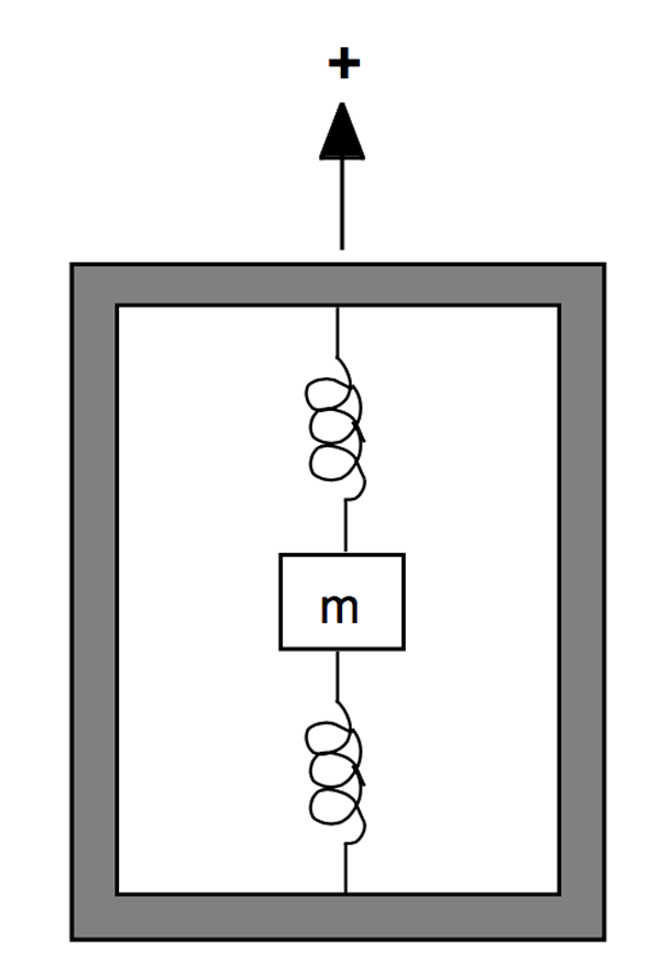
No matter how an accelerometer is constructed, we may think of it as shown in Figure 2. The accelerometer consists of a proof mass, m, suspended from a case by a pair of springs. The arrow indicates the input axis. An acceleration along this axis will cause the proof mass to be displaced from its equilibrium position. This displacement will be proportional to the acceleration. The amount of displacement from the equilibrium position is sensed by a pick-off and scaled to provide an indication of acceleration along this axis. The equilibrium position of the proof mass is calibrated for zero acceleration. An acceleration in the plus direction will cause the proof mass to move downward with respect to the case. This downward movement indicates positive acceleration. Now imagine that the accelerometer is sitting on a bench in a gravitational field. We see that the proof mass is again displaced downward with respect to the case, which indicates positive acceleration. However, the gravitational acceleration is downward. Therefore, the output of an accelerometer due to a gravitational field is the negative of the field acceleration.
Source: Stoval, pg. 5.
Accelerometers measure the deflection of the "proof mass" with something a bit more reliable than a spring. But the point is that we can measure acceleration in any axis.
Inertial Platform
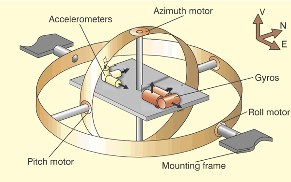
Gimballed inertial platform, from King, figure 1.
An inertial platform is basically three gyroscopes placed at 90° angles with each other and three accelerometers to measure forces on the platform. If we find the forces in each direction over a specific time period, we can find the velocity in all three directions. By multiplying the velocity by time to find distance, a relative position can be determined. If the starting position was known, the relative position can be added to determine an ending position.
Three dimensions – “sort of”
With the three gyroscopes on our inertial platform, we have a way of tracking movement in three dimensions. But we, as pilots, don't actually operate in three dimensions, by the truest sense of the term. Our horizontal plane is aligned with the surface of the earth, which isn't flat.
Our inertial navigation must consider "level" to be parallel to the earth's surface or perpendicular to gravity's pull. The engineer calls this the "locally level frame" but for us pilots it is simply level flight. There are two major problems to tackle. First, the earth is rotating. The inertial navigation system needs to compensate for that. Second, the earth isn’t flat. We have to account for the fact “up” and “down” are technically different everywhere on the globe. Sounds complicated? It is . . .
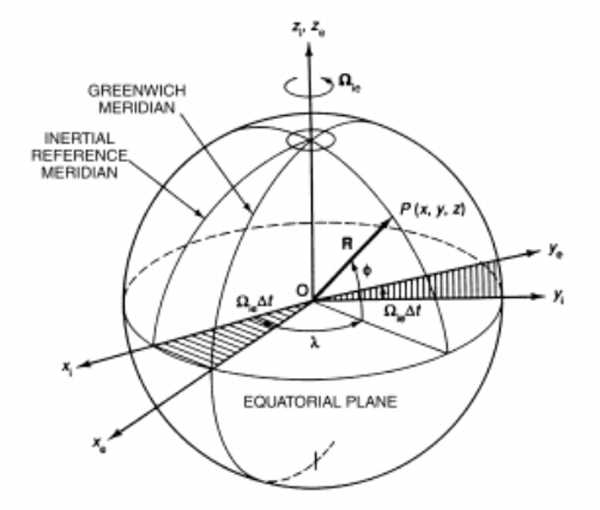
Rotating spherical earth,
Stoval, figure 8.
The next step in our analysis is to allow our spherical earth to rotate. We define a new coordinate frame called the inertial frame, which is fixed at the center of the earth. Ignoring the earth’s orbital motion, we regard the orientation of this frame as fixed with respect to the distant stars. The inertial frame is defined to be coincident with the ECEF frame at zero time. Figure 8 shows the relationship between the inertial and ECEF frames. The ECEF frame rotates with respect to the inertial frame with an angular velocity (Ω) of approximately 15.04 degrees per hour.
Source: Stoval, p. 3
As pilots we don’t need to be concerned with it because the designers have done that for us. So too with the non-flat earth. Since we reference everything on earth to the surface of the earth, the inertial platform must be moved to agree with the "flat earth" concept. If we didn't do this, for example, an airplane flying from Hawaii to Switzerland would show itself inverted at the end of the journey.
Strapdown Systems
Gimballed inertial navigation systems are easy to understand, since each gyroscope maintains its orientation in space no matter what the vehicle is doing. These are called “stable platform systems” since the platform itself is constant. The problem, however, is the gimbal arrangement is mechanically complex and the bearing, motors, and sliprings generate heat and friction. This makes them somewhat expensive to maintain.
Since we are using computers to do much of the work, it isn’t really necessary to keep the platform stable, only to measure the forces on each axis. Most inertial navigation systems today eliminate the gimbals and simply strap the gyroscope to the system case, which is itself strapped to the airplane. Getting rid of the gimbals certainly reduces the number of moving parts and that increases reliability.
The problem is that the sensors used to detect forces on the gyros now have to compensate for the movement of the vehicle itself. But this isn't a problem with modern computers and so the strapdown inertial is pretty much the standard solution today.
Drift errors
With earlier inertial navigation systems, it wasn’t uncommon for the system to wander from its initial position just sitting in the chocks or to develop an error while taxiing to the end of the runway. Friction in gyro bearings, heat in various moving parts, and even the rotation of the earth could introduce errors known as drift. Not too many years ago, a total drift of 3 to 7 miles per hour was not unusual. Replacing the mechanical gyros with light greatly reduced drift.
Ring Laser Gyros (RLGs)
In its most basic form, the RLG body is a solid glass block with three narrow tubes drilled to form a triangle. The tubes are filled with a helium-neon gas mixture and a mirror placed at each end. A neon lamp is used to cause the gas to generate laser light which circulates through the tubes in light particles known as photons. The light beam is split into two and the photons travel in opposite directions. Any movement of the glass block will cause the photons in one direction to arrive sooner or later than the photons going the other direction. The time difference can be used to determine the exact movement of the RLG body.
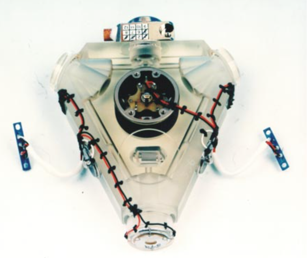
Ring laser gyro photograph,
King, figure 9.
Interestingly enough, the `reliability' advantage of RLGs has turned out to be a fallacy. Good spinning-wheel gyros today have mean time between failures (MTBFs) - in an aircraft environment - of tens of thousands of hours, and virtually no life limiting wearout mechanisms. RLGs are not demonstrably better in either of these respects. In fact, it tends to be the reliability of the associated electronics that dominates an I.N. system's MTBF. A modern strapdown RLG I.N. has an MTBF of 5,000 - 10,000 hours.
Source: King
Hybrid Systems
A new feature for modern inertial navigation systems adds an embedded GPS receiver module, becoming a hybrid system. The result is a system that automatically knows where it is when first initialized, as well as a way to align itself inflight. By constantly checking with GPS, drift errors can be continuously corrected.
4
Flight Management Computer (FMC) “Fail Down” sensor logic
Your FMC will navigate according to what it considers its most reliable sensor, usually GPS. Each system varies and it is important to know which sensor “comes next” in the hierarchy, when the switch is made, and when the system can restore itself to a more reliable source.
A typical system, for example, might have the following hierarchy:
- GPS
- DME/DME
- VOR/DME
- IRS
It may be as simple as saying if the GPS fails, the FMC will revert to DME/DME, if that fails then VOR/DME, and if that fails, finally to the IRS.
Some systems may place margins of accuracy to prevent nuisance switching. If the GPS, for example, is no worse than 5% than DME/DME, the GPS remains the sensor of choice.
With Hybrid Inertial Reference systems, however, it could be that the IRS is considered more reliable, shaking up the hierarchy:
- GPS
- Hybrid IRS
- DME/DME
- VOR/DME
- IRS
It is vitally important to understand what sensors your FMC is using and how the “fail down” hierarchy works.
5
Quantum Global Positioning System
the future?
If you thought going from Inertial Navigation Systems (INS) to Global Positioning Satellite (GPS) systems was a Quantum leap, you are right. Right, that is, if you define Quantum as most people do:
Quantum (everyday usage definition): something revolutionary.
Wrong, however, if you define the word as it comes from the study of physics:
Quantum Mechanics: the branch of physics that describes the behavior of matter and energy at the smallest scales, like atoms, electrons, photons, and other subatomic particles.
A quantum navigation system uses atoms like rubidium or cesium that are cooled to near absolute zero using lasers. Lasers? Yes, shooting a laser beam through these atoms causes the atom to give off energy as the beam exits, and as they lose energy they cool. Why do they need to be cool? The colder the atoms becomes the slower it moves, making measurement easier.
The atoms are then held in "superposition" using magnetic traps. These traps use magnetic fields to essentially suspend the atoms where you want them.
You then shoot the atoms with light pulses from lasers that causes one part of the atom to move up and the other to move down. This is called atom interferometry and is used to measure for acceleration, rotation, and gravitational changes. These measurements are extremely precise and are not subject to the drift found in conventional inertial navigation systems.
For a primer on quantum navigation, see this YouTube video from Dr. Ben Miles: The Genius Behind the Quantum Navigation Breakthough.
Does this discussion make your brain hurt? Maybe a diversion from YouTube is in order: My Brain Hurts.
For quantum navigation systems from a pilots perspective: This Technology Could Revolutionize Airline Safety! (Mentour Now). Skip to the 11:50 minute mark.
I know all this seems like science fiction, but I think we could be seeing this in airplanes before the 2020s are over. I think we as an industry have become too reliant on GPS and the change can't happen fast enough!
References
(Source material)
Basic Principles of Inertial Navigation, Seminar on inertial navigation systems, Tampere University of Technology, undated.
Honeywell Direct-To Newsletter, New FMS Sensor Logic, December 2012.
Honeywell Laseref VI, Micro Inertial Reference System, Product Description, March 2012.
King, A. D., B.Sc, F.R.I.N., Inertial Navigation - Forty Years of Evolution, General Electric Company Review, Vol 13, No 3, 1998.
Stoval, Sherryl H., Basic Inertial Navigation, Naval Air Warfare Center Weapons Division, September 1997.
Wikimedia Commons, Public Domain Artwork