There is much about HF to be confused about. It is a High Frequency (HF), for example, which turns out to be lower than most of the frequencies we deal with on a daily basis.
— James Albright

Updated:
2022-10-28
Younger pilots often hear from the older pilots about just how difficult it was to make a position report "back in the day," but it seems rather easy these days. It is true that technology has made the radios easier to use and the transmitted signals much clearer. But there are still a few things to be gained from learning the technical stuff behind the technology.

1
Frequencies
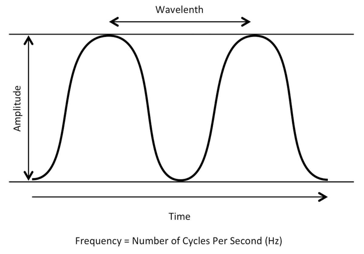
Amplitude, frequency, and wave lengths
Radio Wave Properties
- Radio waves belong to the electromagnetic radiation family, which includes x-ray, ultraviolet, and visible light. Much like the gentle waves that form when a stone is tossed into a still lake, radio signals radiate outward, or propagate, from a transmitting antenna. However, unlike water waves, radio waves propagate at the speed of light. We characterize a radio wave in terms of its amplitude, frequency, and wavelength.
- Radio wave amplitude, or strength, can be visualized as its height being the distance between its peak and its lowest point. Amplitude, which is measured in volts, is usually expressed in terms of an average value called root-mean-square, or RMS.
- The frequency of a radio wave is the number of repetitions or cycles it completes in a given period of time. Frequency is measured in Hertz (Hz); one Hertz equals one cycle per second. Thousands of Hertz are expressed as kilohertz (kHz), and millions of Hertz as megahertz (MHz). You would typically see a frequency of 2,345,000 Hertz, for example, written as 2,345 kHz or 2.345 MHz.
- Radio wavelength is the distance between crests of a wave. The product of wavelength and frequency is a constant that is equal to the speed of propagation. Thus, as the frequency increases, wavelength decreases, and vice versa. Radio waves propagate at the speed of light (300 million meters per second). To determine the wavelength in meters for any frequency, divide 300 by the frequency in megahertz. So, the wavelength of a 10 MHz wave is 30 meters, determined by dividing 300 by 10.
Source: Radio Communications, Chapter 1
The HF Spectrum
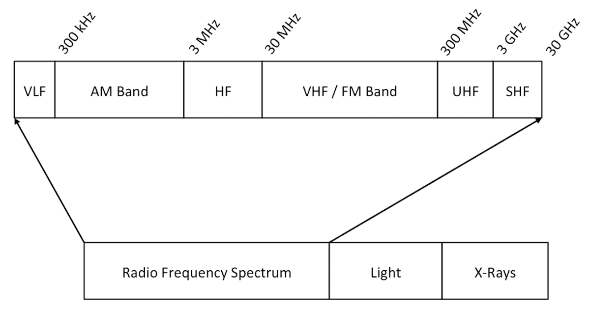
Radio Frequency Spectrum
The HF band is defined as the frequency range of 3 to 30 MHz. In practice, most HF radios use the spectrum from 1.6 to 30 MHz. Most long haul communications in this band take place between 4 and 18 MHz. Higher frequencies (18 to 30 MHz) may also be available from time to time, depending on ionospheric conditions and the time of day.
Source: Radio Communications, Chapter 1
Sidebands
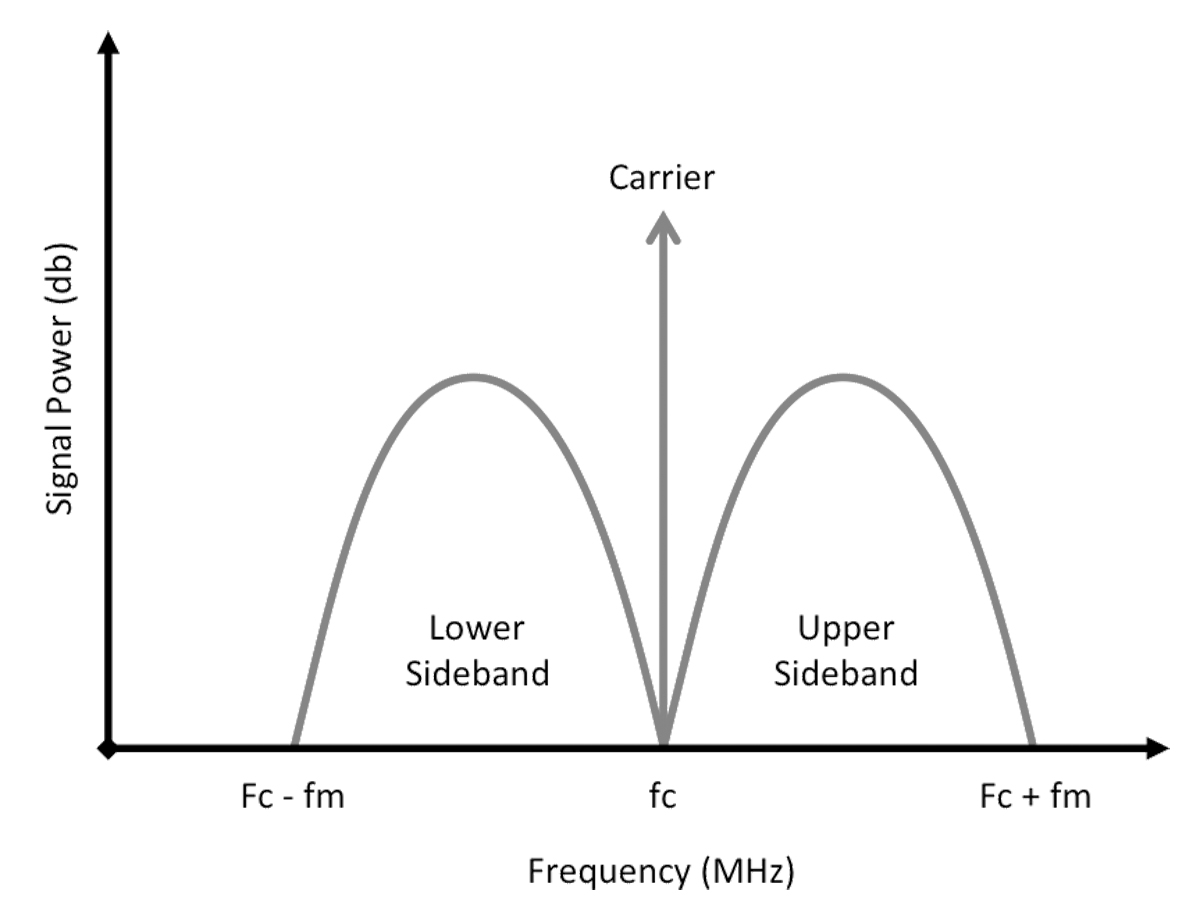
AM Signal Sidebands
Today’s common methods for radio communications include amplitude modulation (AM), which varies the strength of the carrier in direct proportion to changes in the intensity of a source such as the human voice. In other words, information is contained in amplitude variations. The AM process creates a carrier and a pair of duplicate sidebands — nearby frequencies above and below the carrier. AM is a relatively inefficient form of modulation, since the carrier must be continually generated. The majority of the power in an AM signal is consumed by the carrier that carries no information, with the rest going to the information-carrying sidebands.
Source: Radio Communications, Chapter 1
You can think of the data as existing in the fat lobes of the signal where as the center has no space for any data at all. Shortwave radio enthusiasts can use either or both sidebands.
In a more efficient technique, single sideband (SSB), the carrier and one of the sidebands are suppressed. Only the remaining sideband — upper (USB) or lower (LSB) — is transmitted. An SSB signal needs only half the bandwidth of an AM signal and is produced only when a modulating signal is present. Thus, SSB systems are more efficient both in the use of the spectrum, which must accommodate many users, and of transmitter power. All the transmitted power goes into the information-carrying sideband.
Source: Radio Communications, Chapter 1
In aviation we used to note our frequency as "Upper" or "Lower" to differentiate between the two. You would say, "transmitting 8060 upper," for example. All aircraft HF communication, outside of the military, seems to have gravitated to the upper sideband so we no longer need to say it. (It is assumed.)
2
Antennas
My introduction to HF radios were on a KC-135A which had a wire antenna and a radio head with a limited number of crystals used for a limited number of possible frequencies. From there I graduated to a Boeing 707 (EC-135J) with five HF antennas: two wire antennas stretching from two points on the vertical fin to two points on the upper fuselage, and three probe antennas facing forward from the tip of the vertical fin and each wingtip. The transceiver was capable of many more frequencies. We in the cockpit were limited to HF radios using the wire antennas but our radio operators had access to all of them. As pilots, we never used the HF at all. But we had to be schooled on it because of the power required to run them and the power the put out.
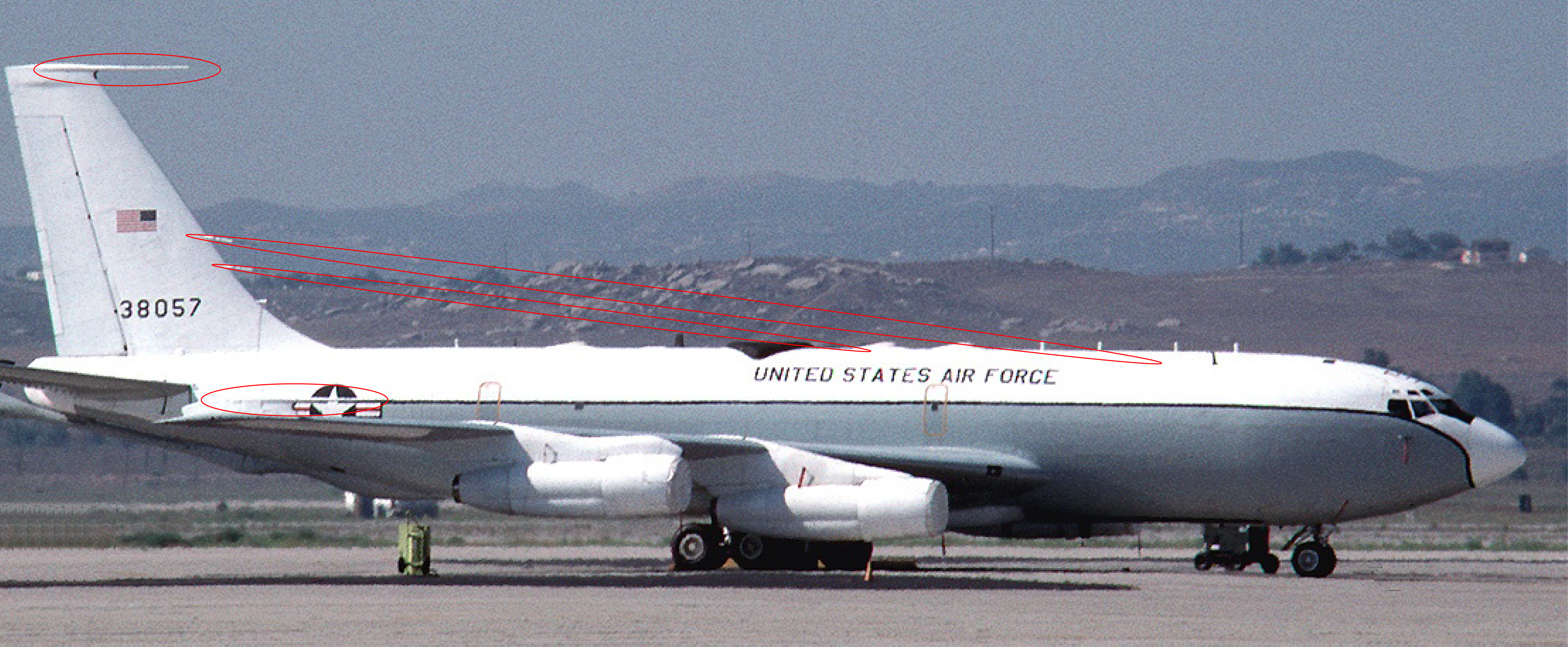
Four HF antennas (2 probe, 2 wires) on my trusty old Boeing 707 (EC-135J)
We had a limitation prohibiting use of the HF transmitter within 15 feet of flammable or explosive materials, during refueling operations or within 300 feet of other aircraft refueling, and within 200 feet of unloaded weapons or warheads. Pretty serious stuff. The aircraft I fly these days have no such limitations. Why is that? There isn't much available on the subject, but looking at a patent of HF transmitters sheds some light.
A shunt antenna mountable on an aircraft comprises a lower plate, an antenna element formed above the lower plate and integrated within a dorsal fin of the aircraft where the antenna element is substantially slant relative to the lower plate; one or more couplers formed on the lower plate and operatively connected to a lower forward end of the antenna element. The couplers transmit radio frequency signals to the antenna element, and the antenna element and the lower plate are separated by air to produce a capacitor effect.
Source: Shunt Antenna Patent, Abstract
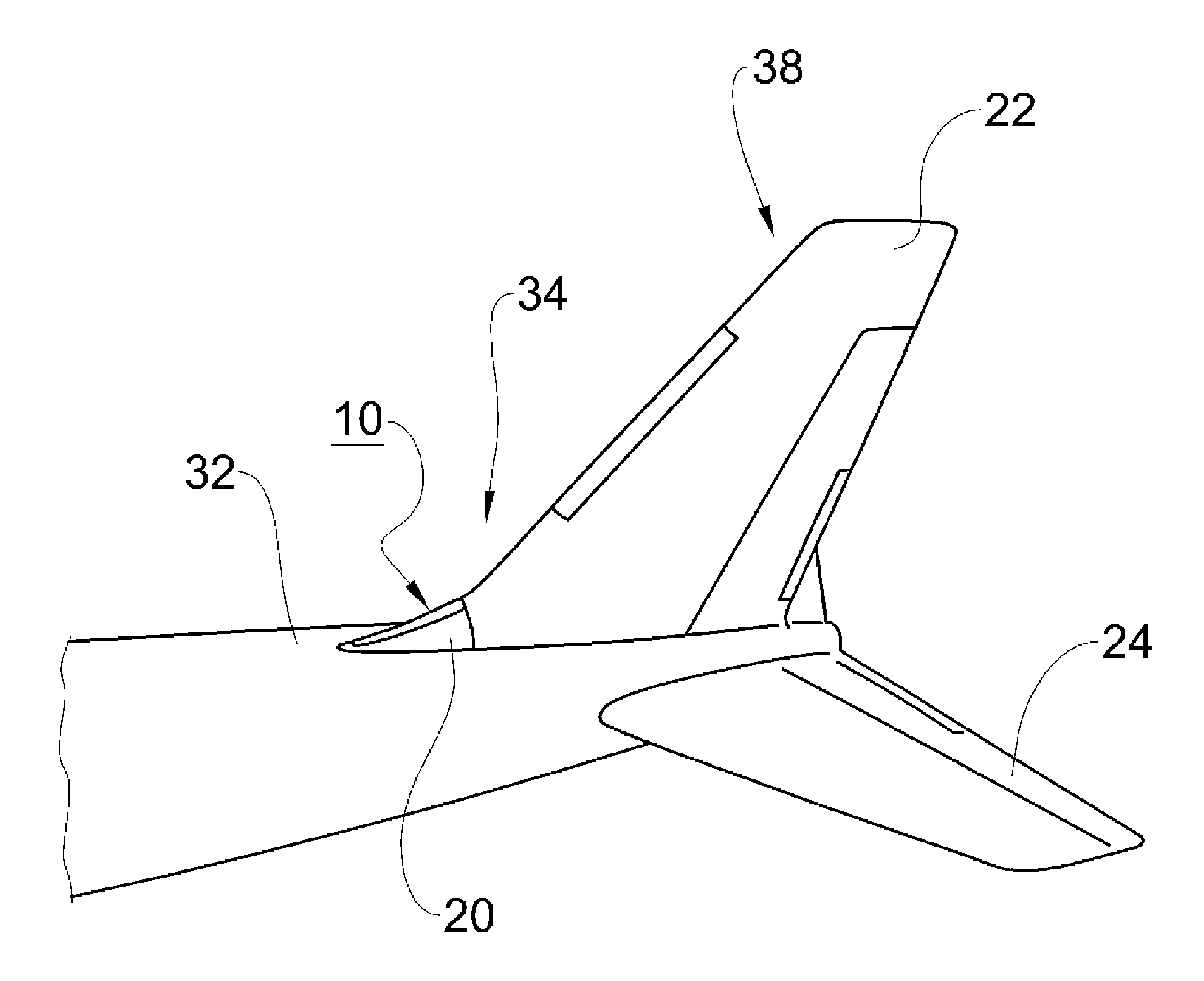
HF shunt antenna outside view (#10), Shunt Antenna Patent, Fig. 1
Source: Shunt Antenna Patent, Background
- Shunt antennas have been used in many places over the years. Basically the term refers to antennas, which are grounded at one end and fed low voltage and high amperage radio frequencies to cause radio frequency propagation from the other end. Shunt antennas fall into this category and they have been used on aircraft vertical tail surfaces for many years. Their use on aircraft tail surfaces causes the whole tail to radiate/receive a high frequency radio signal and results in an almost equal 360 degree propagation or ability to receive a radio frequency (RF) signal.
- The entire tail surface becomes a radiator/receiver of the RF signals from the antenna. The tail surfaces of the aircraft increases the surface area of the antenna and increases the propagation or ability to receive the RF signal in all directions. Prior to the advent of shunt antennas, commercial transport aircraft were equipped with "long wire" antennas whose high-speed capabilities were unacceptable, though used, on the early jets. These antennas were designed to communicate on high frequency ("HF"). A band of frequencies in the range of 2 MHz - 30 MHz designated by international treaty was used for contacts over 200 miles. 2182 kilohertz is the international distress signal.
- A vertical stabilizer HF shunt antenna, which covered most of the band, was developed by Eastern Air Lines (EAL). Such design is found on several Boeing aircraft today. Its failure to cover the lower frequencies is due to its shorter length, which is limited by vertical stabilizer space considerations.
- Most jets now flying internationally use vertical tail mounted HF shunt antennas, with a few installations in wing root fairings, wing tip fairings and wing leading edges. If a long wire HF antenna is used it is generally installed along the length of the fuselage. The dorsal fin HF shunt antenna as designed is installed within the dorsal structure of aircraft to be installed in place of the existing aircraft dorsal. This location maximizes the signal strength both in transmit and receive modes because it uses the adjacent aircraft vertical and horizontal stabilizers as part of the shunt antenna, and the location propagates an extremely good transmit and receive signal forward and aft of the aircraft, which other HF antenna locations do not. This is also very good for radio communications because the aircrew and most ground communications are communications pertaining to where you are going or where you have been.
- The antenna coupler equipment on aircraft is mounted so that it is very close to the antenna element in the dorsal. Shunt antennas work at a lower voltage and a high amperage of 75 Amps plus. This makes long feed lines from antenna coupler to antenna counter-productive due to voltage drop and the consequent power loss. Shunt antennas mounted in the vertical stabilizer mandated mounting the tuners high in the stabilizer in inaccessible or hard to access areas to accommodate this requirement. It would be advantages to mount the tuner units where they should be very close to the feed end of the antenna.
- To achieve these and other objectives, a shunt antenna mountable on an aircraft, comprises a lower plate; an antenna element formed above the lower plate and integrated within a dorsal fin of the aircraft, the antenna element being substantially slant relative to the lower plate; one or more couplers formed on the lower plate and operatively connected to a lower forward end of the antenna element, wherein the couplers transmit radio frequency signals to the antenna element, and wherein the antenna element and the lower plate are separated by air to produce a capacitor effect.
- A feed line is provided to operatively connect the antenna couplers to the antenna element. The feed line is operatively connected to the lower forward end of the antenna element where the antenna element is integrated within a composite structure of the dorsal fin. The aerial separation of the antenna element and the lower plate serves to further produce an inductor effect.
- In an embodiment, the shunt antenna mountable on an aircraft comprises: a lower plate; an antenna element formed above the lower plate and adjacent to a dorsal fin of the aircraft, the antenna element being substantially slant relative to the lower plate; one or more antenna couplers operatively connected to a lower forward end of the antenna element, wherein the antenna couplers transmit radio frequency signals to the antenna element, wherein an aft end of the antenna element is grounded to an empennage of the aircraft, wherein the antenna element and the lower plate are separated by air to produce a capacitor effect, whereby the radio frequency signals from the antenna couplers are guided towards the aft end of the antenna element and into the empennage. Here, there may be further provided a ground plate to furnish a flexible connection between the aft end of the antenna element and the aircraft vertical stabilizer, preferably in a multi-pronged shape.
Source: Shunt Antenna Patent, Background
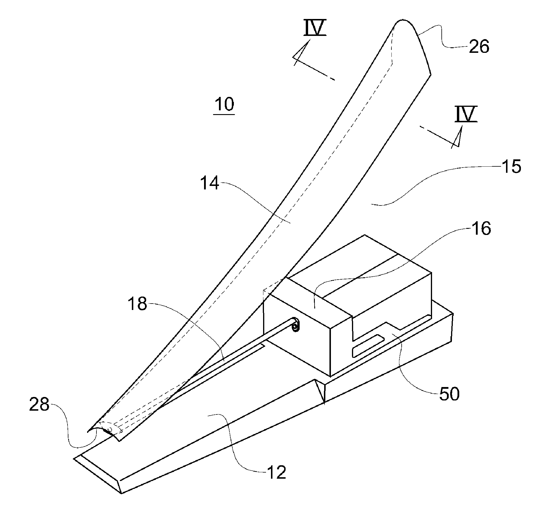
HF shunt antenna inside view, Shunt Antenna Patent, Fig. 3
- As shown therein, the shunt antenna 10 comprises a lower plate 12 that forms a mounting shelf and RF shield, an antenna element 14, antenna couplers 16, feed line 18 connected to the antenna element 14.
- The antenna element 14 is integrated within the composite dorsal skin fuselage.
- The couplers 16 transmit radio frequency (RF) signals to the antenna element 14 via the feed line 18.
- The antenna element 14 and the lower plate 12 become charged by the RF signal substantially separated by air 15, thus the charged antenna element 14 and lower plate 12 separated by air there between serving as an insulator 15 produce a capacitor effect.
- The antenna element 14 has a forward end 28 that is facing towards the nose of the aircraft and an aft end 26 that is closer to the tail of the aircraft. The tail of the aircraft forms the empennage 38, which includes the vertical stabilizer 22 and the horizontal stabilizer 24.
- The lower shelf 12 and the antenna couplers 16 are grounded with the aircraft through the attachment of the dorsal in multiple places located at the aft end of the antenna element and dorsal fin on the top of the aircraft.
Source: Shunt Antenna Patent, Detailed Description of the Preferred Embodiments
Why is this important? I suppose it isn't unless you have damage to the area where the antenna is mounted. The shape of the antenna (14 in the drawings above) relative to the lower plate (12 in the drawings) is critical to maintain a gap for the capacitance effect and to aim the signal into the tail. The tail, in effect, becomes the antenna.
Of course you might be wondering if you have a shunt antenna. I think if it is mounted at the base of the vertical fin, you probably do. My aircraft is so new the manuals haven't got to the HF antenna location yet. But my previous aircraft had this gem in the operating manual:
The shunt antenna is an integrated airframe component mounted in the leading edge of the vertical stabilizer. The antenna element is fed from the dual coupler mount through the copper bus bar. It is electrically tied into airplane’s structure at the top, enabling the entire airplane to act as a low frequency HF antenna.
Source: G450 AOM, §2A-23-30, ¶2.B. (4)
3
Signal propagation
Propagation Paths
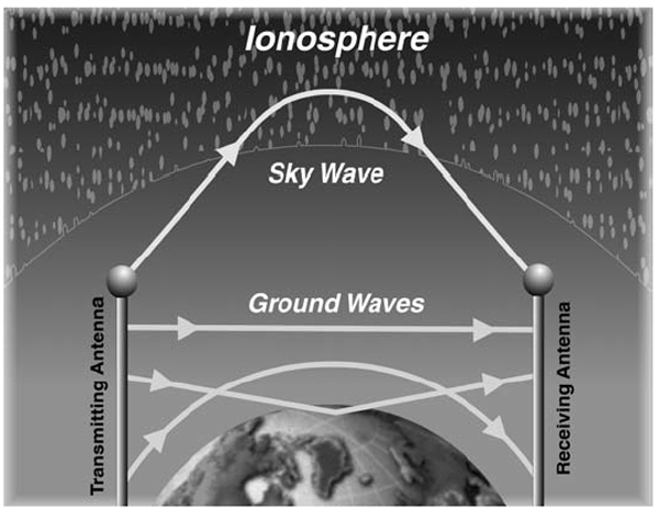
Propagation Paths, from Radio Communications, Figure 1-8.
- Propagation is defined as how radio signals radiate outward from a transmitting source. Radio waves are often believed to travel in a straight line like a stone tossed into a still lake. The true path radio waves take, however, is often more complex. There are two basic modes of propagation: ground waves and sky waves. As their names imply, ground waves travel along the surface of the earth, while sky waves “bounce” back to earth.
- Ground waves consist of three components: surface waves, direct waves, and ground-reflected waves. Surface waves travel along the surface of the earth, reaching beyond the horizon. Eventually, surface wave energy is absorbed by the earth. The effective range of surface waves is largely determined by the frequency and conductivity of the surface over which the waves travel. Absorption increases with frequency.
- Transmitted radio signals, which use a carrier traveling as a surface wave, are dependent on transmitter power, receiver sensitivity, antenna characteristics, and the type of path traveled. For a given complement of equipment, the range may extend from 200 to 300 km over a conductive, all-sea-water path. Over arid, rocky, non-conductive terrain, however, the range may drop to less than 30 km, even with the same equipment.
- Direct waves travel in a straight line, becoming weaker as distance increases. They may be bent, or refracted, by the atmosphere, which extends their useful range slightly beyond the horizon. Transmitting and receiving antennas must be able to “see” each other for communications to take place, so antenna height is critical in determining range. Because of this, direct waves are sometimes known as line-of sight (LOS) waves.
- Ground-reflected waves are the portion of the propagated wave that is reflected from the surface of the earth between the transmitter and receiver.
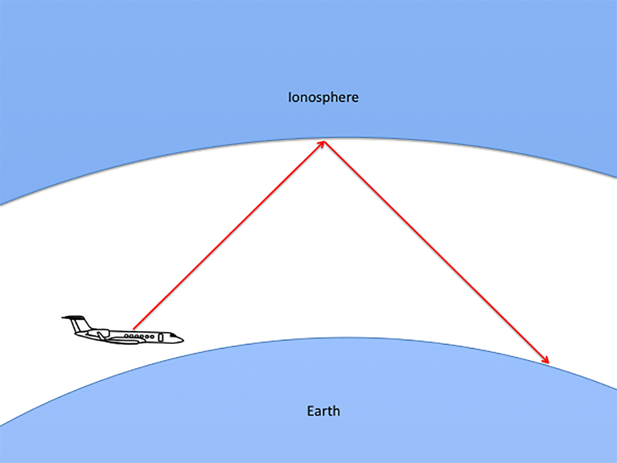
- Sky waves make beyond line-of-sight (BLOS) communications possible. At certain frequencies, radio waves are refracted (or bent), returning to earth hundreds or thousands of miles away. Depending on frequency, time of day, and atmospheric conditions, a signal can bounce several times before reaching a receiver.
Source: Radio Communications, Chapter 1
Line of Sight / Minimum Altitude
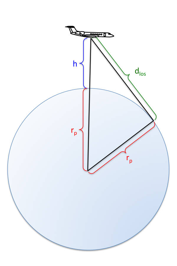
Line of sight
So, at what point does your VHF lose its air-to-ground capability? A little geometry:
Where rp is the radius of the earth (20,025,643 feet at the equator), h is the height of the aircraft, and dlos is the line of sight distance from the aircraft to the horizon. Solving for dlos we get:
Which gives us the line of sight distance available at minimum altitudes:
| Altitude (feet) | Distance (nm) |
| 10,000 | 104 |
| 20,000 | 147 |
| 30,000 | 180 |
| 40,000 | 208 |
| 50,000 | 233 |
You can use your VHF or HF for line of sight communications, but to go beyond the horizon, you will need to bounce an HF signal off the ground, water, or the ionosphere.
Sky Wave Propagation
Sky wave propagation
- The ionosphere is a region of electrically charged particles or gases in the earth’s atmosphere, extending from approximately 50 to 600 km above the earth’s surface. Ionization, the process in which electrons are stripped from atoms and produces electrically charged particles, results from solar radiation. When the ionosphere becomes heavily ionized, the gases may even glow and be visible. This phenomenon is known as Northern and Southern Lights.
- Why is the ionosphere important in HF radio? Well, this blanket of gases is like nature’s satellite, making HF BLOS radio communications possible. When radio waves strike these ionized layers, depending on frequency, some are completely absorbed, others are refracted so that they return to the earth, and still others pass through the ionosphere into outer space. Absorption tends to be greater at lower frequencies, and increases as the degree of ionization increases.
- The angle at which sky waves enter the ionosphere is known as the incident angle. This is determined by wavelength and the type of transmitting antenna. Like a billiard ball bouncing off a rail, a radio wave reflects from the ionosphere at the same angle it hits it. Thus, the incident angle is an important factor in determining communications range. If you need to reach a station that is relatively far from you, you would want the incident angle to be relatively large. To communicate with a nearby station, the incident angle should be relatively small.
Source: Radio Communications, Chapter 2
Ground station HF radio operators worry about the angle of incidence as a way of aiming their signals to a desired distance. Since aircraft are closer to the ionosphere, the achievable angles are far greater as is the achievable distance. The pilot doesn't need to worry about the angle, other than to know how the angle can be affected by atmospheric conditions.
More on that below, under Frequency Selection.
Ionosphere Layers
Ionosphere Layers
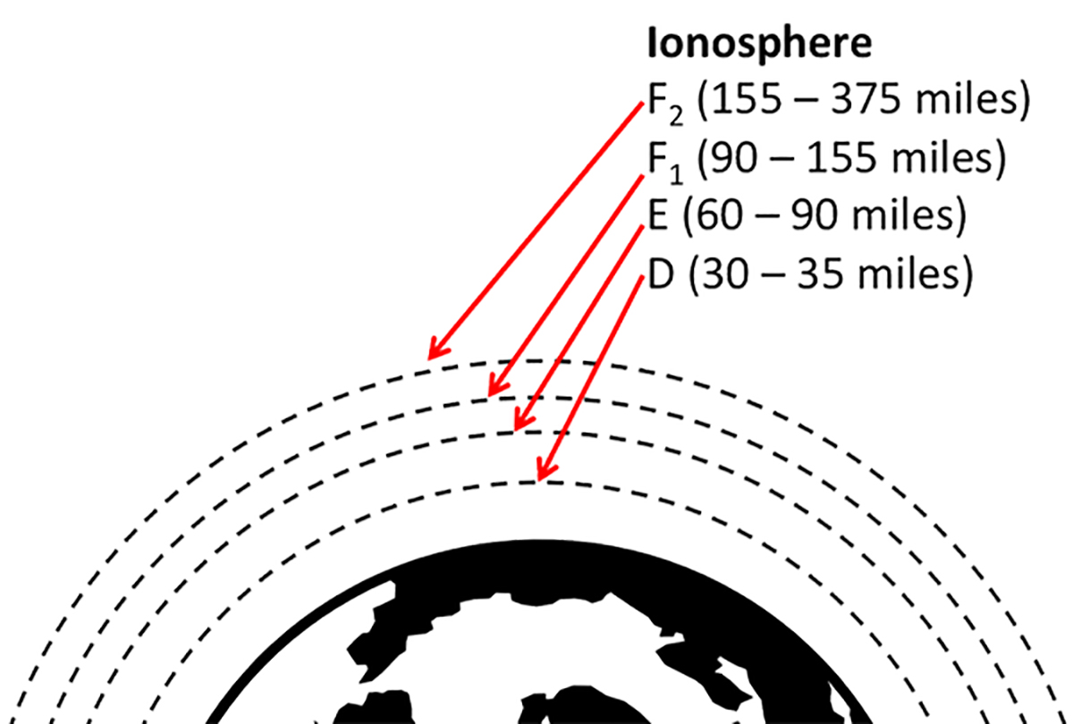
- Within the ionosphere, there are four layers of varying ionization. Since ionization is caused by solar radiation, the higher layers of the ionosphere tend to be more highly ionized, while the lower layers, protected by the outer layers, experience less ionization. Of these layers, the first, discovered in the early 1920s by Appleton, was designated E for electric waves. Later, D and F were discovered and noted by these letters. Additional ionospheric phenomena were discovered through the 1930s and 1940s, such as sporadic E and aurora.
- In the ionosphere, the D layer is the lowest region affecting HF radio waves. Ionized during the day, the D layer reaches maximum ionization when the sun is at its zenith and dissipates quickly toward sunset.
- The E layer reaches maximum ionization at noon. It begins dissipating toward sunset and reaches minimum activity at midnight. Irregular cloud-like formations of ionized gases occasionally occur in the E layer. These regions, known as sporadic E, can support propagation of sky waves at the upper end of the HF band and beyond.
- The most heavily ionized region of the ionosphere, and therefore the most important for long-haul communications, is the F layer. At this altitude, the air is thin enough that the ions and electrons recombine very slowly, so the layer retains its ionized properties even after sunset.
- In the daytime, the F layer consists of two distinct layers, F1 and F2. The F1 layer, which exists only in the daytime and is negligible in winter, is not important to HF communications. The F2 layer reaches maximum ionization at noon and remains charged at night, gradually decreasing to a minimum just before sunrise.
- During the day, sky wave reflection from the F2 layer requires wavelengths short enough to penetrate the ionized D and E layers, but not so short as to pass through the F layer. Generally, frequencies from 10 to 20 MHz will accomplish this, but the same frequencies used at night would penetrate the F layer and pass into outer space. The most effective frequencies for long-haul nighttime communications are normally between 3 and 8 MHz.
Source: Radio Communications, Chapter 2
There are free electrons everywhere and when these electrons attach themselves to molecules in the atmosphere these molecules are said to be ionized. An ionized molecule is good for bouncing radio waves so an ionized layer of atmosphere is good for long distance communications. Where the knowledge shown here comes in handy is when selecting a frequency. During the day the lowest ionosphere is as ionized as it gets and a higher frequency (with the shortest wavelength) bounces best. During the night this layer isn't so effective so you want to pass through it. So a lower frequency (with a higher wavelength) will pass through the D layer on its way to the F layers where a better bounce can be had. That validates the old pilot's rule of thumb: the higher the sun, the higher the frequency.
Atmospheric Ionization Factors
- The intensity of solar radiation, and therefore ionization, varies periodically. Hence, we can predict solar radiation intensity based on time of day and the season, and make adjustments in equipment to limit or optimize ionization effects.
- Ionization is higher during spring and summer because the hours of daylight are longer. Sky waves are absorbed or weakened as they pass through the highly charged D and E layers, reducing, in effect, the communication range of most HF bands.
- Because there are fewer hours of daylight during autumn and winter, less radiation reaches the D and E layers. Lower frequencies pass easily through these weakly ionized layers. Therefore, signals arriving at the F layer are stronger and are reflected over greater distances.
- Another longer term periodic variation results from the 11-year sunspot cycle. Sunspots generate bursts of radiation that cause higher levels of ionization. The more sunspots, the greater the ionization.
- During periods of low sunspot activity, frequencies above 20 MHz tend to be unusable because the E and F layers are too weakly ionized to reflect signals back to earth. At the peak of the sunspot cycle, however, it is not unusual to have worldwide propagation on frequencies above 30 MHz.
- In addition to these regular variations, there is a class of unpredictable phenomena known as sudden ionospheric disturbances (SID), which can affect HF communications as well. SIDs are random events due to solar flares that can disrupt sky wave communication for hours or days at a time. Solar flares produce intense ionization of the D layer, causing it to absorb most HF signals on the side of the earth facing the sun.
- Magnetic storms often follow the eruption of solar flares within 20 to 40 hours. Charged particles from the storms have a scattering effect on the F layer, temporarily neutralizing its reflective properties.
Source: Radio Communications, Chapter 2
4
Required for oceanic?
Yes, you can use your SATCOM for position reporting if you really needed to, and yes, you do make position reports with CPDLC. But the requirement remains: you need the HF when beyond VHF coverage. You need at least one, you might need two if you don't have CPDLC or a qualified satellite voice system.
U.S. Requirement
Equipage with CPDLC does not eliminate the requirement for operable two-way radios. For most oceanic operations this means operable HF radios are required.
Source: AC 91-70B, ¶4.4. Note 2
ICAO Requirement
An aircraft operated as a controlled flight shall maintain continuous air-ground voice communication watch on the appropriate communication channel of, and establish two-way communication as necessary with, the appropriate air traffic control unit, except as may be prescribed by the appropriate ATS authority in respect of aircraft forming part of aerodrome traffic at a controlled aerodrome.
- Note 1. SELCAL or similar automatic signaling devices satisfy the requirement to maintain an air-ground voice communication watch.
- Note 2. The requirement for an aircraft to maintain an air-ground voice communication watch remains in effect after CPDLC has been established.
Source: ICAO Annex 2, §3.6.5.1
Aircraft shall be equipped with suitable instruments and with navigation equipment appropriate to the route to be flown.
Source: ICAO Annex 2, §5.1.1
North Atlantic Requirement
Within the NAT Region, aircraft equipped for SATCOM voice shall restrict the use of such equipment to emergencies and non-routine situations. An unforeseen inability to communicate by voice radio constitutes a non-routine situation. Since oceanic traffic typically communicates through aeradio facilities, a SATCOM call due to an unforeseen inability to communicate by other means should be made to such a facility rather than the ATC centre unless the urgency of the communication dictates otherwise. Dedicated SATCOM telephone numbers (short codes) for aeradio facilities and air traffic control facilities are published in national AIPs.
Source: ICAO Doc 7030, §NAT, ¶3.4.1
How Many HF's Do I Need?
The regulations now address long-range communication requirements in terms of LRCS. With that as a basis, an aircraft on extended range segments unable to utilize line-of-sight systems must have at least two operational LRCSs to honor regulatory communication requirements (unless specifically excepted under the operational rules).
Source: FAA MMEL Policy Letter (PL)106
This is the first document from the FAA that says you need two long range communications systems. We in the could get away with just one HF as our only means of long range communications until this came out. Now, "unless specifically excepted," if you don't have a qualified SATVOICE or CPDLC, you need two HFs.
The "unless specifically excepted under the operational rules" refers to Operations Specification B045, which does allow a single LRCS under some circumstances:
OpSpec/MSpec/LOA B045 authorizes a certificate holder/program manager/operator to operate with a functional Single Long-Range Communication System (SLRCS) in the specific area of en route operations defined in this OpSpec/MSpec/LOA and then referenced in a certificate holder/program manager/operator’s OpSpec/MSpec/LOA B050. Title 14 CFR part 1, § 1.1 defines a long-range communication system (LRCS) as: “a system that uses satellite relay, data link, high frequency, or another approved communication system which extends beyond line of sight.”
Source: FAA Order 8900.1, §B045, ¶A
If you are interested in this exception, I encourage you to investigate B045. It is limited to the special provisions area of the Gulf of Mexico and parts of the western Atlantic:
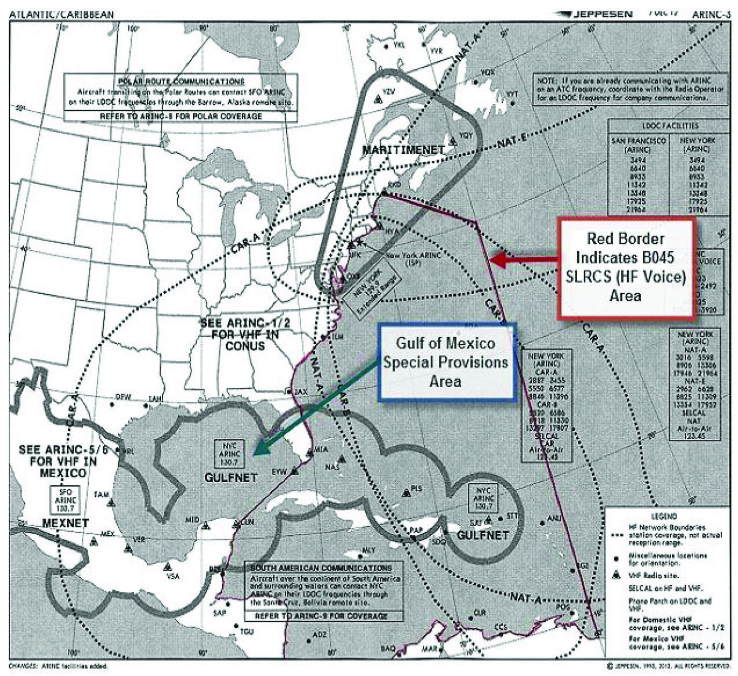
Single LRCS map, FAA Order 8900.1, §B045, figure 3-70
There are other limitations and I encourage you to seek out the 8900.1 series for more. To do this, load the FAA Dynamic Regulatory System, type in B045, and look for 8900.1. The use the search function for B045.
5
Frequency selection
Effects of Skywave Paths, from HF Communications Transceiver Pilot's Guide, Figure 1-1.
- Because HF radio waves depend upon the ionosphere for reflection, their propagation is affected by changes in the ionosphere. It is changes in the density of the electrically charged particles in the ionosphere which cause propagation to improve or deteriorate. Since the ionosphere is formed primarily by the action of the sun’s ultraviolet radiation, its thickness changes in relation to the amount of sunlight passing through it. Sunlight-induced ionization increases the particle density during the day and the absence of it reduces the particle density at night. At midday, when the sun’s radiation is at its highest, the ionosphere’s thickness may expand into four layers of ionized gas. During the nighttime hours, the ionosphere diminishes, normally merging into just one layer.
- A good rule of thumb for the time of day is that the higher frequencies are best during daylight (10 to 29.9999 MHz) and lower frequencies work best at night (2 to 10 MHz).
- This rule of thumb can be explained by a mirror analogy. It is the electrically charged particles in the ionosphere which reflect or bend radio waves back toward earth like a mirror reflects light. Sunlight induces ionization and increases the density of these particles in the ionosphere during the day. The mirror becomes thicker and it reflects higher frequencies better. When the sun goes down the density of charged particles decreases and the ionosphere becomes a mirror that can only reflect lower frequencies in the HF band.
Source:

Higher frequencies are best when the sun is up (above 10 MHz) and lower frequencies work best when the sun is down (below 10 MHz).
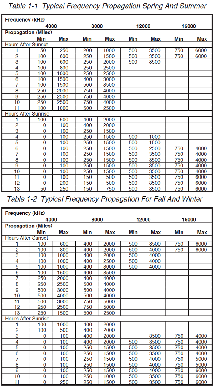
Maximum usable frequencies, (HF Communications Transceiver Pilot's Guide, Tables 1-1 and 1-2)
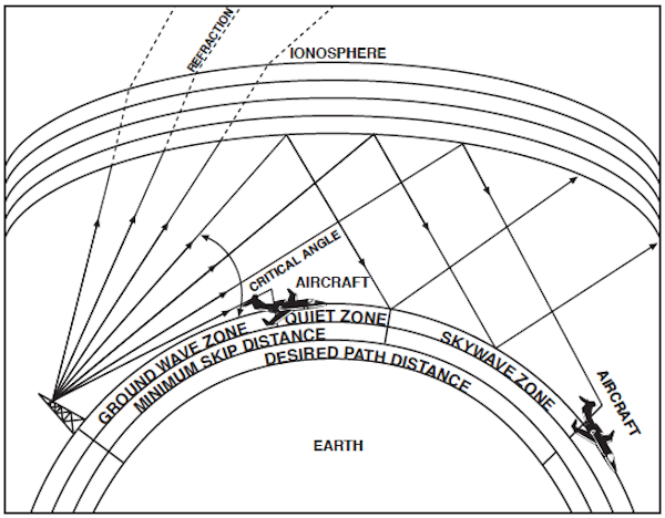
For any one particular frequency, as the angle at which an HF radio wave hits a layer of the ionosphere is increased, a critical angle will be reached from which the wave will just barely manage to be reflected back to earth. Waves entering at sharper angles than this will pass through this layer of the ionosphere and be lost in space (or may reflect off another layer of the ionosphere). Changing the frequency under the same conditions will change the critical angle at which the HF radio waves will be reflected back to earth. The highest frequency which is reflected back to the earth is called the maximum usable frequency (MUF). The best HF communications are usually obtained using a frequency as close to the MUF as possible since radio waves higher than this frequency are not reflected and radio waves lower than this frequency will be partially absorbed by the ionosphere.
Source: HF Communications Transceiver Pilot's Guide, pages 1-3 to 1-5
If experiencing HF communications difficulty, select the highest available frequency based off the maximum usable frequency table.
You should also be aware of the possibility that you or the ground station you are calling may be in a quiet zone. The linear distance from the point of transmission to the point where the skywave returns to earth is called the skip distance. There may be a quiet zone between the end of the ground wave and the return of the skywave. No communication can take place in this area. At any time, day or night, there is a “window” of usable frequencies created by the reflecting properties of the ionosphere. At night this “window” will normally be in the lower range of HF frequencies, and during the day it will be in the higher range of frequencies.
Source: HF Communications Transceiver Pilot's Guide, pages 1-3 to 1-5
If HF conditions have been good and a particular frequency appears to be unusable, that frequency's "bounce" may place the receiving station in a quiet zone. Pick a frequency of great enough difference to change the "bounce."
6
What can you do with HF?
Of course we make position reports (or at least check our SELCAL) with HF, but there are other uses too.
Air Traffic Control
We are used to getting our HF frequency assignment from someone on VHF or data link. You can predict the frequency on a few charts. There are other sources, such as: https://radio.arinc.net/atlantic/, which as of this writing reflects the following:
- Alaska/North Pacific (West of 150W): (Primary) 6655 kHz, (Secondary) 5628 kHz
- Asia to and from Hawaii: 8843 kHz and 5574 kHz
- California to Hawaii tracks: 8843 kHz (Primary), (Secondary) 5574 kHz
- Coastal VHF Carolinas to Florida and Gulf of Mexico: 130.70 MHz
- Coastal VHF Maritime Canada to Virginia: 129.90 MHz
- Eastern Atlantic: (Primary) 8825 kHz, (Secondary) 6628 kHz
- Extended Range VHF LAX/SFO/ACV/Hawaii/Guam: 131.95 MHz
- Guam Area: (Primary) 8870 kHz, (Secondary) 5652 kHz
- Gulf of Mexico / S. America: (Primary) 6586 kHz, (Secondary) 5520 kHz
- Gulf of Mexico / S. America: (Primary) 6586 kHz, (Secondary) 5520 kHz
- Hawaii to Alaska: (Primary) 11282 kHz, (Secondary) 5547 kHz
- Hawaii to California tracks: (Primary) 8843 kHz, (Secondary) 5574 kHz
- Hawaii to Pacific NW tracks: (Primary) 11282 kHz, (Secondary) 5547 kHz
- Hawaii to Southbound: (Primary) 5643 kHz, (Secondary) 8867 kHz
- Hawaii to Westbound: (Primary) 6532 kHz, (Secondary) 3455 kHz
- Mazatlan Airspace: (Primary) 8843 kHz, (Secondary) 5574 kHz, (Tertiary) 6640 kHz
- North America to Asia: (Primary) 11282 kHz, (Secondary) 5547 kHz
- North America to South Pacific: (Primary) 8843 kHz, (Secondary) 5574 kHz
- Northeast U.S.: (Primary) 3455 kHz, (Secondary) 5550 kHz
- On-ground LAX: 131.95 MHz
- On-ground SEA/PDX: 131.80 MHz
- On-ground SFO: 130.40 MHz
- On-ground YVR: 129.40 MHz
- Pacific NW to Hawaii tracks: (Primary) 11282 kHz, (Secondary) 5547 kHz
- Polar Route 6640 kHz: (Primary) 3494 kHz, (Secondary) 6655 kHz
- San Francisco ARINC SatVoice: 436625
Emergency Frequency
HF 2182 / 4125
Position Reports
Time Hack
Before the days of GPS the frequencies were crawling with time hack stations. Most of those, alas, are gone. The frequencies 5000, 10000, 150000, and 25000 got you something almost everywhere in the world. These days those frequencies are pretty much just in the United States, but you might get lucky.
The National Institute of Standards and Technology (NIST) broadcasts on the following frequencies from the locations noted:
| Frequency (MHz) | Latitude | Longitude |
| 2.5 | 40°40'52.2" N | 105°02'31.3" W |
| 5 | 40°40'42.1" N | 105°02'24.9" W |
| 10 | 40°40'47.8" N | 105°02'25.1" W |
| 15 | 40°40'45.0" N | 105°02'24.5" W |
| 20 | 40°40'53.1" N | 105°02'28.5" W |
Weather
VOLMET Aviation Weather Broadcasts Worldwide
- AFI Brazzaville h+00, h+30 10057, 13261
- EUR Shannon h+00, h+30 3413, 5505, 8957, 13264
- NAT Gander h+20, h+50 3485, 6604, 10051, 13270
- New York h+00, h+30 3485, 6604, 10051, 13270
- PAC Anchorage h+25, h+55 2863, 6679, 8828, 13282
- Hong Kong h+15, h+45 2863, 6679, 8828, 13282
- Honolulu h+00, h+30 2863, 6679, 8828, 13282
- Tokyo h+10, h+40 2863, 6679, 8828, 13282
- Auckland h+20, h+50 2863, 6679, 8828, 13282
- SAM Buenos Aires h+25, h+55 5601
- Ezeiza h+15 2881, 5601, 11369
- SEA Sydney h+00, h+30 6676, 11387
- Bombay h+25, h+55 2965, 6676, 11387
- Calcutta h+05, h+35 2965, 6676, 11387
- Singapore h+20, h+50 6676, 11387
- Bangkok h+10, h+40 2965, 6676, 11387
7

Dear Code7700,
I was a little embarrassed the other day when I told our chief pilot not to test the HF radio while we had a fuel truck hooked up, because it was an aircraft limitation. He told me I was wrong, so I bet him a cup of coffee. Long story, short: I lost. Looking back at all my previous airplanes, none in the last ten or twenty years had such a limitation. In fact, I think only my Air Force aircraft were so restricted. What gives? Is it okay to use the HF during refueling operations?
Mr. Richard Fader
Fort Lee, N.J.
Dear Mr. Fader,
I don't see any problem with being cautious whenever you have a fuel truck hooked up to the airplane, but if you are flying something of recent vintage without any limitations prohibiting use of the HF, it is a safe bet the manufacturer considered this. So why have things changed over the years and why was it different in your previous military experience?
There was probably a very real concern with long wire and wingtip mounted probe antennas. Many of these antennas could have high voltage potentials at their ends or tips and sparking/arcing may have been a real possibility.
I do not think it is a concern at all with the notch or shunt antennas installed on modern aircraft. These antenna are current fed and are grounded to the airframe. Because the antenna is at the same potential as the airframe, sparking/arcing is not really an issue.
If these warnings persist, it could be holdover / tribal knowledge from the military, where munitions and warheads were at risk of detonating due to stray high powered radio frequencies. You should obviously obey any limitations for your aircraft, military or civilian.
Sincerely,
Larry, a friend of Code 7700
Dear Code 7700,
My HF radio has a switch position for AM, yet we only ever use USB. I get why USB is better. So why do we have an AM position at all?
Mr. Richard Fader
Fort Lee, N.J.
Dear Mr. Fader,
In my opinion, the short answer is you would probably never need to use AM mode for transmitting. Most all aircraft HF SSB communications are conducted in the upper sideband (USB) mode. It is however useful for receiving. Unfortunately, after researching this topic thoroughly, I cannot give you a definitive answer, but offer some framework as to why the AM button is there.
A short history lesson gives some perspective. It started with the Royal Mail Ship (RMS) Titanic disaster on May 31, 1911. In response to that disaster, grew the International Maritime Treaty SOLAS, Safety of Life at Sea, first adopted as the Convention of Safety of Life at Sea, and signed at London, January 20, 1914.
SOLAS in its successive forms is generally regarded as the most important of all international treaties concerning the safety of merchant ships. SOLAS 1974 (as amended) requires flag states to ensure that ships flagged by them comply with the minimum safety standards in the construction, equipment and operation of merchant ships.
Today we have international bodies, such as ICAO, the International Telecommunications Union (ITU), and the International Maritime Organization (IMU) working together to coordinate aeronautical, aircraft, ship and coast stations (radio stations). This includes radio equipment requirements and regulations. This coordination is promulgated by international treaty and law. In the United States for example, radio equipment is approved for sale and authorized for use by the Federal Communications Commission (FCC).
High frequency transceivers can be used for voice communications, (radiotelephony), digital transmissions such as HFDL (high frequency datalink), selective calling, (SELCAL), ALE (automatic link establishment), search and rescue, distress, emergency, urgency or safety communications, public correspondence (marine operator, radiotelephone calls, radiotelegrams, landline phone patch) and shortwave listening (news, weather and entertainment). Some of these purposes use AM, such as SELCAL. SELCAL and shortwave broadcasts from ground stations are transmitted in AM. Further, U.S. Code of Federal Regulations, 47 CFR § 87.131 authorizes aircraft communications using AM mode on marine frequencies for public correspondence.
According to the Allied Signal (Bendix/King) HF Communications Transceiver KHF 950/990 Pilot’s Guide (Rev. 0, Dec 1996): “Most all aircraft HF SSB communications are conducted in the USB Mode. Some ground stations continue to use the AM mode, but those stations are being phased out in favor of the more efficient SSB mode of operation.”
This statement, at the time of printing (1996) could be referring to "resource limited" states (countries) that have or had only AM (not SSB) radios in their coast/maritime stations.
Nevertheless, including AM is probably good business. It helps create a successful, versatile radio product.
To drive sales, a manufacturer attempts to build a radio system that is adaptable enough to be used in a variety of aircraft, both military and civilian, fixed wing and rotary. Here are some of the current fixed wing installations for the Rockwell Collins HF-9000D system:
"Gulfstream III/IV/V, Challenger 601/604, Global Express, Canadair RJ, Beechjet 400, Falcon 20/50, Falcon 900/2000, Saab 2000 BAE 125-800, C-130, CASA CN-235/212/295, Atlantic, Lear 55, EMB-145, U-2"
In summary, AM can be used to transmit on the International distress frequency of 2182 KHz, for public correspondence on marine frequencies, and for radiotelephony with stations that may not yet be equipped with SSB equipment. Also, it can be used to receive shortwave broadcasts and time signals such as WWV or CHU. AM is used internally by the radio to receive SELCAL transmissions (they are received even when the button/knob is set to USB or any other mode), and can be used for ALE purposes.
I hope this information has been helpful and responsive to your question.
Sincerely,
"Sparks," a fried of Code 7700
References
(Source material)
Advisory Circular 91-70B, Oceanic and International Operations, 10/4/16, U.S. Department of Transportation
Gulfstream G450 Aircraft Operating Manual, Revision 35, April 30, 2013.
HF Communications Transceiver Pilot's Guide, KHF 950/990, Allied Signal Aerospace, Rev 0, Dec 96
ICAO Annex 2 - Rules of the Air, International Standards, Annex 2 to the Convention on International Civil Aviation, July 2005
ICAO Doc 7030 - Regional Supplementary Procedures, International Civil Aviation Organization, 2 2008
Radio Communications In the Digital Age, Volume 1, HF Technology, Edition 2, Harris AssuredCommunications, October 2005
Shunt Antenna for Aircraft, United States Patent, US 7,511,674 B2, Mar. 31, 2009, Duane K. McNutt
Please note: Gulfstream Aerospace Corporation has no affiliation or connection whatsoever with this website, and Gulfstream does not review, endorse, or approve any of the content included on the site. As a result, Gulfstream is not responsible or liable for your use of any materials or information obtained from this site.