The pilots of British Airways Flight 38 did well to get the airplane on the ground with only one serious injury to its occupants and there is little to critique about their performance. What interests me in this are the lessons drawn by Gulfstream for the G550 and the new information about fuel "stickiness."
— James Albright

Updated:
2014-10-03
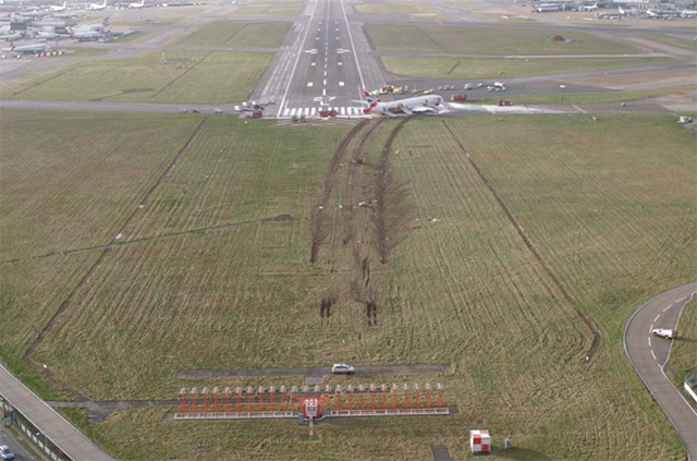
British Airways Flight 38,
from AAIB, figure 1.
The Boeing 777 carries a lot of fuel and incorporates a water scavenging system to eliminate water in the fuel tanks. It does not have a heated fuel return system similar to what is found in the G550. Where the aircraft are similar is they both have Rolls-Royce engines controlled by Full Authority Digital Engine Control (FADEC), where a computer determines thrust levels based on more than just pilot inputs. Gulfstream's reaction to this mishap was to mandate the heated fuel return system be turned off at top of descent. I'm not sure how the heated fuel return system can introduce ice into the fuel system.
The Accident Report did an excellent job showing that cold fuel tends to adhere to its surroundings between -5°C and -20°C and is most "sticky" at -12°C. These are common fuel tank temperatures for both the G450 and G550.
The mishap aircraft's fuel flow demands increased four times on approach, times corresponding to flap and gear drag increases. The fuel temperature following a very cold en route and descent phase was just increasing into the "sticky" range. The fuel filters just prior to the fuel pumps clogged with ice, causing the engine rollbacks. It could be worth considering delaying approach and landing until fuel temperature increases out of the "sticky" range if flying an airplane prone to fuel system icing.

1
Accident report
- Date: 17 January 2008
- Time: 1242
- Type: Boeing 777-236ER
- Operator: British Airways
- Registration: G-YMMM
- Fatalities: 0 of 16 crew, 0 of 136 passengers
- Aircraft Fate: Damaged beyond repair
- Phase: Landing
- Departure Airport: Beijing Capital Airport (ZBAA)
- Destination Airport: London Heathrow Airport (EGLL)
2
Narrative
- Whilst on approach to London (Heathrow) from Beijing, China, at 720 feet agl, the right engine of G-YMMM ceased responding to autothrottle commands for increased power and instead the power reduced to 1.03 Engine Pressure Ratio (EPR). Seven seconds later the left engine power reduced to 1.02 EPR. This reduction led to a loss of airspeed and the aircraft touching down some 330 m short of the paved surface of Runway 27L at London Heathrow. The investigation identified that the reduction in thrust was due to restricted fuel flow to both engines.
- It was determined that this restriction occurred on the right engine at its Fuel Oil Heat Exchanger (FOHE). For the left engine, the investigation concluded that the restriction most likely occurred at its FOHE. However, due to limitations in available recorded data, it was not possible totally to eliminate the possibility of a restriction elsewhere in the fuel system, although the testing and data mining activity carried out for this investigation suggested that this was very unlikely. Further, the likelihood of a separate restriction mechanism occurring within seven seconds of that for the right engine was determined to be very low.
Source: AAIB, page 2.
3
Analysis
Boeing 777-200ER Fuel System
- The fuel on the Boeing 777-200ER is stored in three fuel tanks: a centre tank, a left main tank and a right main tank. The centre tank contains two override / jettison pumps (OJ) and each main fuel tank contains two boost pumps, identified as forward and aft. Each of the pump inlets is protected by a 1⁄4 inch mesh screen and the pumps are equipped with a check valve fitted in the discharge port, to prevent fuel in the fuel feed manifold flowing back through the pump. A pressure switch, mounted between the pump's impeller and check valve, monitors the fuel pressure and triggers an advisory warning in the flight deck if the pressure rise across the pump drops below a value, of between 4 and 7 psi.
Source: AAIB, ¶1.6.8
The G450/G550 fuel boost pumps are also in a tank within the fuselage and are also protected by a non-bypassable filter.
- The fuel feed manifold runs across the aircraft and connects to the engine fuel feed lines. The manifold is split between the left and right system by two cross-feed valves, identified as forward and aft. When these valves are closed, and the centre tank is the source of the fuel, the left OJ feeds the left engine and the right OJ feeds the right engine. The fuel from the left and right main tanks supply their respective engines during main tank feed. Spar valves in the fuel manifold provide a means of shutting off the fuel supply to the engines.
- To prevent large amounts of 'free water' building up in the fuel tanks, the aircraft is fitted with a water scavenge system that uses jet pumps operated by motive flow from the OJ and boost pumps. One jet pump is located in each main tank and there are two in the centre tank. In the main fuel tanks the jet pumps draw fluid from the lowest sections of each tank and inject it close to the inlet of each aft boost pump. In the centre tank, fluid is drawn from the lowest section of the tank and injected close to the OJ inlets.
Source: AAIB, ¶1.6.8
The G450/G550 have no such system, but are also not known to accumulate fuel tank water.
- The FOHE serves the dual purpose of cooling the engine oil and raising the temperature of the fuel so that ice does not affect the downstream components, including the LP filter and the Fuel Metering Unit (FMU). The FOHE is a hybrid cross-flow / counter-flow design and it includes a matrix of fine tubes. The fuel enters the top of the FOHE and passes through the tubes; the hot oil enters the FOHE main body and passes around the fuel tubes.
- The temperature of the fuel after it has passed through the FOHE is considerably above its entry temperature. The FOHE matrix consists of over 1,000 small tubes that are crimped at various locations along their length to improve thermal transfer efficiency. The crimps at the inlet of the tubes are to a slightly smaller diameter than the remainder of the crimps to prevent small debris becoming lodged in the matrix. The tubes protrude by approximately 4 mm from the matrix top plate, which separates the fuel from the oil, and therefore extend into the fuel in the inlet chamber.
Source: AAIB, ¶1.6.8
- During the testing, a restriction at the fuel boost pump inlet screen was achieved on six occasions sufficient to restrict the flow: on one occasion the force on the ice distorted the inlet screen. These restrictions appeared to have occurred as a result of the method by which water was introduced into the fuel to maintain the required concentration; consequently these restrictions were considered to be an artifact of the test set-up. The restrictions were all characterised by a drop in the fuel pressure, sufficient to generate the boost pump low fuel pressure warning, and a reduction in the electrical current draw of the boost pump.
- The only occasion when it appeared that there might be a sufficient quantity of ice to block a pipe occurred when approx 6 litres of water had been injected into the boost pump inlet over a period of 7 hours. During this period the flow rate was maintained at 6,000 pph and the water content varied between 100 and 150 ppm. On dismantling the system a large ball of soft ice was found just down stream of the spar valve on a coupling that is not used on the aircraft. Despite the presence of the ice, no pressure drop was detected across this section of tube whilst the fuel was flowing at 6,000 pph.
Source: AAIB, ¶1.16.5.5
Fuel Flow Demands on Final Approach
- As the flaps reached the 30° position the airspeed had reduced to the target approach speed of 135 kt and the autothrottle commanded additional thrust to stabilise the airspeed. In response to variations in the wind velocity and associated airspeed changes, there followed a series of four, almost cyclic, thrust commands by the autothrottle. It was during the fourth acceleration, and as additional thrust was being commanded, that the right engine, followed some seven seconds later by the left engine, experienced a reduction in fuel flow. The right engine fuel flow reduction occurred at a height of about 720 ft and the left engine at about 620 ft. Just prior to the reduction in right engine fuel flow, about 2.5 nm from the runway, the flight crew were visual with the runway and the copilot became pilot flying.
- Of the four thrust commands it was the second that resulted in the highest delivery of fuel flow, reaching a peak of 12,288 pph for the left engine and 12,032 pph for the right. These peaks occurred about 26 seconds prior to the reduction in fuel flow to the right engine. Peak fuel flows during the first and third thrust commands were lower, at about 9,500 pph and 9,000 pph respectively.
- During the fourth thrust increase, the right engine fuel flow had increased to 8,300 pph before gradually reducing. The recorded EPR then started to diverge from the commanded EPR and the right engine FMV opened fully. Some seven seconds later, the left engine fuel flow, which had increased to 11,056 pph, also started to reduce and the left engine FMV also moved to its fully open position. The QAR record ended shortly after.
- Fuel temperature at the time of the fuel reduction to both engines was -22°C. Since commencing the descent, TAT had risen by 43°C and was now 11°C.
- As the left engine fuel flow had decreased, a slight stagger in the position of the thrust levers occurred, with the left lever leading the right. It was at this time, at a height of about 590 ft and about 48 seconds prior to impact with the ground, that the flight crew started to become aware of an anomaly, with the copilot noticing the split in the thrust lever positions. The thrust lever stagger occurred as a result of the autothrottle system entering an alternate mode, termed 'TRA dot'.
- Several seconds later, the thrust levers were then realigned as the autothrottle continued to advance both levers towards the maximum thrust position. A few seconds later the automatic 500 ft Radio Altimeter callout occurred.
Source: AAIB, ¶1.11.2
Fuel System Ice Accumulation
- [Tests] demonstrated that, with normal concentrations of dissolved and entrained water present in aviation turbine fuel, ice can form around the inside of the fuel feed pipes. The accumulation of ice appeared to be dependent on the velocity of the fuel, and the fuel and environmental temperatures. The testing established that in certain environmental conditions ice can accumulate in the fuel system when the fuel is at a temperature between +5°C and -20°C, with ice appearing to accumulate at a lower rate at -20°C. Whilst very little ice accumulates at -35°C, ice which has accumulated at warmer temperatures will stay attached to the pipe walls as the temperature is reduced to -35°C with no apparent change in its properties. These results are consistent with the earlier laboratory tests undertaken by the aircraft manufacturer, as well as previous research on the formation of ice in aircraft fuel systems. This work identified that there is a 'sticky range' between approximately -5°C and -20°C, where ice will adhere to its surroundings with ice being at its most 'sticky' at around -12°C.
- The tests carried out in the environmental fuel test rig then demonstrated that increasing the fuel flow can result in the release of a quantity of ice sufficient to restrict the fuel flow through the FOHE. An increase in the TAT, which occurs when the aircraft descends, results in an increase in the temperature in the strut, which the tests proved could also cause ice to be released from the fuel pipes in the strut area.
- It was also evident, from all the fuel rig testing, that ice can move through the fuel feed system and under very low flow conditions might collect in areas such as the fuel pipes in the strut, which form a low point when the aircraft is in its normal cruise attitude, and the LP pump inlet. It was observed during these tests that, apart from the inlet screens and the FOHE, restrictions to the fuel flow did not occur in any of the other fuel system components nor were any features identified in the fuel system which would cause a large enough concentration of ice to accumulate and cause a restriction.
Source: AAIB, ¶1.11.2
4
Cause
The investigation identified the following probable causal factors that led to the fuel flow restrictions:
- Accreted ice from within the fuel system released, causing a restriction to the engine fuel flow at the face of the FOHE, on both of the engines.
- Ice had formed within the fuel system, from water that occurred naturally in the fuel, whilst the aircraft operated with low fuel flows over a long period and the localised fuel temperatures were in an area described as the 'sticky range'.
- The FOHE, although compliant with the applicable certification requirements, was shown to be susceptible to restriction when presented with soft ice in a high concentration, with a fuel temperature that is below -10°C and a fuel flow above flight idle.
- Certification requirements, with which the aircraft and engine fuel systems had to comply, did not take account of this phenomenon as the risk was unrecognised at that time.
Source: AAIB, page 2.
References
(Source material)
Accident to Boeing 777-236, G-YMMM at London Heathrow Airport on 17 January 2008, United Kingdom, Department of Transport, Air Accident Investigation Branch, Report 1/2010.