When this accident happened in 1990 many of us flying aircraft with far less automation thought the cause was pilots who surrendered their control to the computers and that this kind of thing could never happen to us. As most of the aviation world has followed the Airbus example of highly automated cockpits, more and more of us are discovering that it can indeed happen to us.
— James Albright

Updated:
2023-10-22

Indian Airlines 605 wreckage
Stephen Lanfermeijer (tailstrike.com)
As is typical with many Airbus accident reports, the lawyers got involved and if you read from cover to cover you discover what happened, but not why. I didn't realize this when I first read the report because I was flying a Boeing where it could not have happened. Now, decades later, the why has become clear. More about that after the report itself.

1
Accident report
- Date: 14 Feb 1990
- Time: 1303
- Type: Airbus A320-321
- Operator: Indian Airlines
- Registration: VT-EPN
- Fatalities: 4 of 7 crew, 92 of 146 passengers
- Aircraft Fate: Destroyed
- Phase: Approach
- Airport: (Departure) Mumbai Airport, India (VABB)
- Airport: (Destination) Bangalore-Hindustan Airport, India (VOBG)
2
Narrative
- On Feb 14th, 1990, Indian Airlines Flight 605, an Airbus A320-231 (Registration VT-EPN), was operating a scheduled passenger flight from Bombay to Bangalore, India. The Captain in the left seat was flying the aircraft and was undergoing the first of 10 route checks required for qualification to Captain. A check airman was flying in the right seat. There were 7 crew members and 139 passengers on board the aircraft. The flight from Bombay to the Bangalore was uneventful. The weather at Bangalore was good, with landings being conducted on runway 09. The flight crew initially planned for a VOR DME approach to runway 09, but subsequently accepted vectors for a visual straight-in approach.
- Initially, the airplane was properly configured for a manual approach and landing, but during the approach, the flight crew made a number of incorrect flight guidance mode selections that led to an extremely low airspeed and low thrust condition in the final stages of the approach. The flight crew did not detect the unusually low airspeed and thrust until a point from which a successful recovery would not be possible. The airplane descended below the planned glide slope and crashed into a golf course, approximately 2800 feet short of the runway, and burst into flames. Four of the seven crewmembers (including both pilots), and 88 of 139 passengers died in the crash.
- During the descent, the flight was cleared by approach control (ATC) for a visual approach, rather than the planned VOR DME approach. A visual approach allows the flight crew to fly the approach without primary reference to flight instruments, and to plan their approach track and flight path visually, in order to arrive at the end of the runway for landing. Flight recorder data indicated to the investigators that just before reaching seven miles from the airport, with the autopilot still connected, the flight crew activated the autopilot approach mode. Activating the approach is unique to Airbus aircraft and is a Flight Management Guidance System (FMGS - autopilot) feature which automatically commands slower aircraft airspeeds, if in the Managed Speed Mode, which is normally the case, during an approach. Commanded/managed speeds will appropriately reduce airspeed to the respective flap maneuvering speed as configuration is changed for landing. Investigators determined from the cockpit voice recorder that the managed approach speed was 132 knots, and this was verified and cross checked by the flight crew. Various airplane configuration changes were subsequently made (flaps and landing gear) while continuing the descent to 4600 feet as cleared by ATC.
- Seven miles from the runway, with the runway in sight, the flight crew disconnected the autopilot and contacted Bangalore Tower.
- During the visual approach, with the crew manually flying the airplane, both the left and right flight directors remained engaged, even though the flight directors were not necessary for the visual approach. Use of the flight director during a visual approach was not prohibited in A320 procedures manuals.
- Investigators determined that throughout the approach, until the accident, the flight crew made a number of errors in flight control unit and flight director settings that resulted in both engines remaining at idle for an extended period of time, and allowed the airspeed to decay until reaching a point where a thrust increase was automatically commanded by the airplane flight control protection modes. During this period, the airplane slowed from the targeted approach speed of 132 knots down to 106 knots. According to the investigation, as the airplane reached 114 knots, engine thrust was automatically increased toward go-around power. At about the same time, the flight crew, at about 106 knots, recognized the impending impact short of the runway and advanced the throttles to go-around power.
- At this point, the time required for the engines to accelerate to go-around power was insufficient to arrest the descent, and the airplane impacted the ground on the Karnataka Golf Course, about 2800 feet before the approach end of the runway. Following this initial impact, the airplane bounced once over a ravine, impacted a second time, and then struck a 12 foot embankment causing both the engines and the landing gear to separate. The airplane came to rest just outside the Bangalore Airport boundary wall, and burst into flames. Four of seven crewmembers (including both pilots) and 88 of the 139 passengers died as a result of the accident.
Source: FAA Lessons Learned
Back when I was flying cockpits with much less automation, I thought "managed speed mode" was a bridge too far. It took control away from the pilots and encouraged laziness. Now that I have been flying aircraft that control aircraft speed according to configuration, I realize that it is a safety feature that reduces pilot workload so he or she can concentrate on keeping ahead of the airplane. But it does encourage laziness.
3
Analysis
The aircraft
The Airbus Industrie A320 [ . . .] was the first commercial aircraft to be certified with Fly- By-Wire (FBW) flight controls. Two sidesticks, left and right, are used for manual flight path control. Two non-backdriven thrust control levers on the center aisle stand facilitate engine thrust control through the auto-flight system. The A320 is configured with a combined flight management and auto-flight system which provides flight control guidance to the autopilots and the flight director displays on the Primary Flight Displays and also for engine thrust control. It was also one of the first aircraft to be configured with a "Glass" Flight Deck comprised of six cathode ray tube displays and with an Electronic Centralized Aircraft Monitoring (ECAM) system which facilitates management of aircraft systems and provides alerts and checklist guidance in case of system abnormalities. The A320 is certified to be flown with a two person crew.
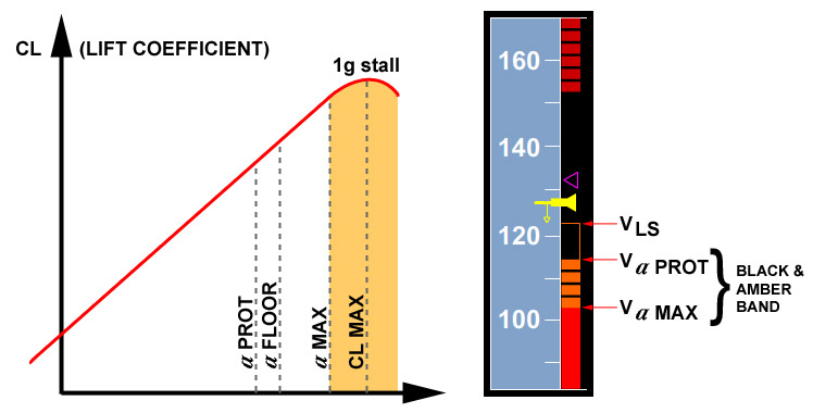
The A320 PFD is laid out in the standard Basic T configuration with attitude in the center, airspeed on the left, altitude on the right, and heading below the attitude display. The airspeed display provides a real time display of actual airspeed, airspeed trend (increasing or decreasing), and airspeed upper and lower limits based on aircraft configuration. Actual airspeed is depicted by a white/yellow airspeed reference line overlaid on the center of a moving airspeed ladder. Also, decelerating or accelerating, a yellow speed trend arrow will display on the reference line. The length of the trend arrow is indicative of the rate of deceleration or acceleration, with the tip of the arrow showing the speed the aircraft will reach in 10 seconds if its deceleration/acceleration remains constant. The target airspeed is presented by a triangle on the airspeed tape – in magenta if "managed" by the Flight Management System (FMS), or in blue if "selected" by the pilot on the Flight Control Unit (FCU). In this accident, the target airspeed was "managed" by the FMS and was set at 132 knots.
Source: FAA Lessons Learned
While all of this seemed revolutionary at the time, many aircraft these days have adopted some, most, or all of these changes to basic aircraft design. Of particular note for this accident and lessons for current aircraft is that the lines between the flight director and autopilot have been blurred. How you manipulate the flight director impacts how the airplane itself flies. Also noteworthy: the throttles do not move in response to the commands of all those computers. You do not get tactile information from the throttles.
Low speed protections
High angle of attack protection
When the A320 is in the normal flight control law (as was the case in this accident), the lower end of the airspeed tape will display unique limit speeds; VLS, Alpha Prot, and Alpha Max.
- Minimum Selectable Speed (VLS) - The top of the amber strip along the speed scale indicates VLS. It represents the lowest selectable speed providing an appropriate margin to the stall speed. For the landing approach configuration, VLS is 1.23 times the aircraft stall speed (VS - not shown on the Airspeed Tape).
- Alpha Protection Speed (Alpha Prot) - The top of a black and amber strip along the speed scale indicates Alpha Prot. It represents the speed corresponding to the angle of attack at which alpha protection becomes active. Until reaching Alpha Prot, the A320 pitch control is in a load factor demand (G-command) mode, and operates with apparent neutral speed stability, meaning that there are no changes in longitudinal forces with changes in airspeed (longitudinal stick force changes are basically zero throughout the normal flight envelope). Pitch trim is automatic in the normal airspeed range and there is no requirement for the pilot to make pitch trim changes for airspeed changes. This automatic pitch trim freezes when alpha Prot becomes active. Below Alpha Prot, pitch control reverts to an alpha command mode and aft longitudinal stick forces increase as speed slows and angle of attack (alpha) increases. In this accident, Alpha Prot activated as the airplane decelerated through 114 knots.
- Alpha Max Speed - The top of a red strip along the speed scale indicates Alpha Max Speed. It represents the speed corresponding to the maximum angle of attack that the aircraft can attain in the normal control law of the flight control system, even if the pilot were to pull the sidestick to the aft control stop.
Under normal flight control law, when the angle of attack becomes greater than Alpha Prot, the FCS switches elevator control from normal mode to a protection mode in which angle of attack is proportional to sidestick deflection. In the Alpha Prot range (Alpha Prot to Alpha Max), the sidestick commands angle of attack directly. However, the angle of attack will not exceed Alpha Max, even if the pilot gently pulls the sidestick all the way back. If the pilot releases the sidestick, the angle of attack returns to Alpha Prot and stays there. This protection against stall and windshear has priority over all other protections. The autopilot disconnects at Alpha Prot + 1°.
Speeds for Alpha Prot, Alpha Floor, and Alpha Max vary according to the weight and the configuration. To deactivate the angle of attack protection, the pilot must push the sidestick forward more than 8°, or more than 5° if alpha is less than Alpha Max.
Alpha Floor is an autothrust feature designed to aid the flight crew in recovery from high angle of attack, low airspeed situations. Alpha Floor is available in all flight phases down to 100 feet Radar Altimeter during landing, when the flight control system is in the Normal Flight Control mode.
When Alpha Floor is triggered, the autothrust system automatically increases thrust to TOGA thrust regardless of thrust lever position or autothrust engagement status. "A. FLOOR" displays on PDF FMA Column 1 and on the engine displays. Alpha Floor is a function of angle of attack and therefore, it is not depicted on the PFD airspeed tape.
Source: FAA Lessons Learned
Because the pilots do not manually trim the pitch of the aircraft under normal conditions, the switch from VLS to Alpha Prot may cause the pilots to allow the pitch to decrease since they are not accustomed to a stick that is no longer neutral.
Flight Control Unit (FCU)
Primary pilot interface with the auto-flight system is via the Flight Control Unit (FCU) mounted centrally on the flight deck glare shield. The FCU contains Auto-pilot (AP1/AP2) and Auto-thrust (A/THR) selection pushbuttons in the center of the FCU. Flight Director (FD) Selector pushbuttons are located outboard of the FCU left and right. Each FD pushbutton only controls display of the FD for its respective side PFD.
The FCU is configured with four knobs which facilitate pilot manual selection of auto-flight speed, roll (lateral), and pitch (vertical) modes. The knobs can be individually pushed to "push" that segment of auto-flight guidance over to being "managed" by the Flight Management System (FMS). Under "Managed" Guidance, the aircraft is guided along a pre-programmed route, vertical, lateral, and speed/Mach profile. FMS flight plan, navigation, performance, and speed/altitude constraint data are pre-programmed or modified via one of the two Multi-Function Display and Control Units (MCDU) located on the center aisle stand forward of the throttle levers.
Any of the four FCU knobs can be pulled to "pull" that segment of auto-flight control to the pilot ("selected" guidance) where the pilot can dial in the desired Speed, Heading/Track, Altitude, or Vertical Speed/Flight Path Angle and override the FMS managed guidance for that segment of auto-flight guidance. During "Selected" Guidance, the aircraft is guided to a "selected" target which is set by the pilot in the FCU. It is possible to fly in a mixed mode configuration, where, for example, lateral guidance of the pre-programmed flight plan route is being "managed" by the FMS but the speed and vertical guidance is “selected" by the pilot.
"Selected" guidance always overrides "managed" guidance. During the Indian Airlines Flight 605 accident sequence, the Speed mode was being "managed" by the FMS and the lateral heading mode (HDG) and the Altitude (ALT) and Vertical Speed (V/S) modes were "selected" by the aircrew. If the autopilot is engaged, standard procedure for many airlines is for the pilot flying the aircraft to make FCU selections. If the pilot flying has disengaged the auto-pilot and is flying manually (as was the case for the Indian Airlines 605 accident sequence), the pilot not flying will make FCU selections/changes when commanded by the pilot flying. Normal operational procedure is to verify that FCU changes are accepted by the auto-flight system by confirming that the PDF FMA annunciation changes are consistent with what was selected on the FCU.
For the A320, the vertical modes can also be "managed" by the FMS where the aircraft will follow a preprogrammed vertical altitude and speed profile. In the "managed" mode, intermediate altitude constraints will be honored as the aircraft climbs or descends toward the FCU target altitude. The aircraft must be in a "managed" lateral mode (flying along a preprogrammed route of flight) in order to be able to be in a "managed" vertical mode. If lateral mode is "selected", then, by system design, the vertical mode must also be in a "selected" mode. The vertical mode can be "managed" or "selected" when the lateral mode is "managed". When the vertical mode is "selected" by the aircrew, the aircraft will climb or descend directly to the FCU target altitude and ignore any intermediate FMS altitude constraints. During the accident sequence, the vertical mode was "selected" such that the descent would continue uninterrupted to the target altitude set in the FCU.
Source: FAA Lessons Learned
When we fly very simple airplanes we learn almost intuitively that the stick impacts airspeed even more than the throttle. Even a complex airplane with very basic automation drills that connection because we have tactile experience reinforcing it. Aircraft with autothrottles capable of doing all the throttle work from takeoff to landing can ingrain in the pilot the idea that the airspeed just takes care of itself. In the case of this accident, the airplane was making power setting decisions in accordance with what the software thought was needed, but the airplane's lateral and vertical commands were coming from the pilot, who wasn't aware the throttles were not using the same rules.
Open or variable thrust
During both the "managed" and "selected" vertical modes, the Autothrust system can be in a fixed thrust ("Open") mode or in a "Variable" thrust mode. In the "Open" mode, autothrust is set to full climb thrust for an open climb (OPEN CLB) or to idle thrust for an open descent (OPEN DES). Airspeed is controlled by adjusting aircraft pitch, commanded either by the autopilot when it is engaged, or by the flight directors when the pilot is flying manually. The aircraft will stay in the OPEN mode until the FCU target altitude is reached or if the aircrew selects a "variable" thrust climb or descent mode.
For an OPEN descent to stay active, either the Autopilot, or at least one of the Flight Directors must be selected ON. If the Autopilot and both Flight Directors are OFF, the thrust mode will default to a "variable" thrust mode and engine thrust will be adjusted to maintain target airspeed. If the pilot is manually flying in the OPEN mode, the autoflight system expects the pilot to be following flight director pitch guidance in order to maintain airspeed. If flight director pitch guidance is not followed, large speed deviations will occur.
The normal method of selecting an Open Mode is to select the desired altitude in the FCU window and to "pull"/ "select" the Altitude knob. If the selected altitude is higher than current altitude, Open Climb (OP CLB) will engage and engine thrust will increase to full climb power. If the selected altitude is lower than current altitude, Open Descent (OP DES) will engage and engine thrust will decrease to idle power.
In the variable mode, autothrust will adjust engine power output to maintain the target airspeed, and pitch will be adjusted to maintain a target vertical speed or flight path angle. Variable mode thrust is the appropriate desired thrust mode during final approach. Variable mode will be active whenever a vertical path of some sort is being followed (ILS Glide Path or the Vertical Navigation (VNAV) path of the FMS programmed descent/approach profile), when vertical speed is selected, and/or when there is NO autoflight guidance (auto-pilot and flight directors OFF).
When manually flying a visual approach, A320 aircrews are trained to turn off BOTH Flight Directors to insure that variable thrust is enabled and modulated to maintain target airspeed. If only one Flight Director is turned off, the Flight Director Bars will be removed from that respective side PFD, but thrust will NOT default to variable thrust. The PFD FMA autoflight status will still show one flight director as being engaged.
Source: FAA Lessons Learned
The "open" versus "variable" modes are fairly standard in the world of autothrottles, though most manufacturers don't use this terminology. In fact, some manufacturers don't address this at all. In the early days of autothrottles, some would call the open mode "speed on the elevator." In open mode, the throttles are either at maximum power available or idle, and airspeed was controlled with the elevator.
What is particular to Airbus is the interconnection of the Flight Director bars to the autothrottles. If only one pilot deselects the FD, the throttles will remain in open thrust. In other words, if either flight director is on, the system assumes the pilot is using the flight director to control speed.
Autothrust system
Thrust control is predominantly accomplished through the autothrust system which is part of the A320 autoflight system. The autothrust system is engaged by arming the autothrust system (THR pushbutton on the FCU panel in flight, or selecting TOGA or FLX for takeoff) and placing the engine thrust levers into the active autothrust range (just above the idle stop up through and including the CL detent when both engines are running; just above the idle stop up through and including the Max Continuous Thrust (MCT) detent for single engine operations). For normal autothrust operation, the thrust levers are placed in the required detent and left there for that phase of flight – TOGA for takeoffs and go-arounds, FLX for reduced thrust takeoffs and for single engine operations, and CL (Climb) for all other two engine phases of flight (climb, cruise, descent, and approach).
The autothrust system is notably different from other transport category aircraft thrust control systems in that the thrust levers are set to a detent, are not normally moved out of the detent, and do not have an autothrust backdrive for the thrust levers. The thrust levers do not move in response to engine thrust changes. The thrust levers remain in the selected detent position until moved by the flight crew. During approach to landing, the autothrust system is disengaged by retarding the thrust levers to the idle stop. The pilot is prompted to do this by a "RETARD, RETARD" aural callout just prior to landing.
When the autothrust system is active, the thrust levers remain stationary as thrust varies. The autothrust system and autothrust commands are based totally upon autoflight flight guidance. Autoflight flight guidance is active if the autopilot or either flight director is ON. When the pilot is flying manually and at least one flight director is ON, and the autothrust OPEN mode is active, the autothrust system expects that the pilot to follow flight director commands. If the PFD flight director command bars are not followed, large speed deviations may occur. Unless a crew member intervenes, the airspeed deviations will increase until additional autoflight and flight control system protections are reached. Therefore it is critical that pilots fly with both FD’s ON or both FD’s OFF.
Source: FAA Lessons Learned
The "both FD's ON or both FD's OFF" has caused other Airbus accidents. It makes you wonder why there are two FD switches or why pressing one doesn't automatically actuate the other.
Sequence of events

Altitude - Speed and EPR, Canadian Engineering Report, fig 13.
- During the initial stages of the descent into Bangalore, the autopilot was engaged in "Idle – Open Descent" mode, and the crew discussed their plans to conduct a VOR DME approach. While 42 miles from the airport, ATC identified the airplane on radar, and began issuing maneuvering instructions for a visual approach to runway 09, rather than the crew’s planned VOR DME approach. After passing through 8500 feet, the flight crew activated the approach mode, and verified that the managed approach speed was 132 knots. ATC cleared the flight to 4600 feet, and that altitude was properly set into the FCU as a target level off altitude.
- Seven miles west of the airport, and with the runway in sight, the autopilot was disconnected, and the flight crew contacted Bangalore tower. The flight director and autothrust systems remained engaged, and remained in the "Idle – Open Descent" mode, as the airplane was still descending toward 4600 feet. As the airplane passed through 5000 feet, the ALT* mode activated to capture and level off at 4600 feet. The Pilot not flying (PNF) announced the mode change to the pilot flying (PF), as annunciated on the PFD.
- In response, the PF then requested "OK, give me go around" to which the PNF asked "Go around you want?" and the PF stated "6000" (meaning the Go-Around Altitude of 6000’ as shown on the approach plate). The PNF did not acknowledge the "6000" but instead asked "Or do you want Vertical Speed" (meaning the Vertical Speed vertical mode). The PF responded, "Vertical Speed". At DFDR time 247, the PNF asked "How Much?", and the PF stated "1000" which was acknowledged by the PNF. Vertical speed mode was then selected and the aircraft entered the Speed/Vertical Speed mode. Investigators believed that sometime during these events, the PNF also likely reset the Altitude Target to 3300 feet, rather than the previously requested 6000 foot go around altitude.
- At DFDR time 261, the PF again requested, "Go around, 6,000", but this was not acknowledged by the PNF who was busy getting landing clearance from Bangalore tower. At DFDR time 276, the aircraft was still in the Vertical Speed Mode with a Managed Speed of 132 knots. It descended in vertical speed mode through the visual 3 degree descent path to runway 09 at about 1000 feet AGL (3900 feet MSL).
- At DFDR time 292, and about 600 feet above the ground (~3500 feet MSL), the ALT* Vertical Mode again activated. The aircraft was below the visual glide path, with a descent rate of about 1000 feet per minute, in Speed Mode for Thrust, and speed was about 136 knots. Investigators believed that activation of the ALT* Mode was most likely because the PNF had selected the VOR DME MDA altitude of 3300 feet.
- At DFDR time 295, the PF then requested, "OK, 700 feet rate of descent" (meaning set the Vertical Speed Mode to 700 feet per minute rate of descent). Instead of acknowledging the "700 feet rate of descent", the PNF commented, "Missed Approach is …..". Also, at this same time, flight recorder data indicated that the Autothrust mode went from "1" to "0" (Open/Idle).
- During the 3 seconds between 600 feet and 512 feet above the ground (DFDR 292 to 295), changes occurred in the FMGS Vertical Mode that, upon reaching 512 feet, resulted in the aircraft being in the Idle/Open Descent Vertical Mode with engine thrust reducing to idle. The accident report stated, "the most probable cause for the engagement of idle/open descent mode was that instead of selecting a vertical speed of 700 feet per minute at the relevant time, i.e., about 35 seconds before the first impact, the (PNF) had inadvertently selected an altitude of 700 feet which was well below the runway altitude."
- The investigation then concluded "identification of the cause for the engagement of idle/open descent mode on short final approach during the crucial period of the flight is not possible". However, the following probable scenarios were cited by the investigation, and presented in the accident report;
- "the most probable cause for the engagement of idle/open descent mode was that instead of selecting a vertical speed of 700 feet per minute, the PNF had inadvertently selected an altitude of 700 feet (the vertical speed and altitude selection knobs of the Flight Control Unit (FCU) are close to each other). The altitude of 700 feet that got selected in this manner was lower than the aircraft altitude at that time and therefore the aircraft had gone into idle/open descent mode.
- The PNF dialed the wrong (Altitude) knob (thinking that he dialed the Vertical Speed knob) resulting in the selection of a lower altitude ...... It was probable that he wanted to select go around altitude but the words just told to him by the PF regarding vertical speed, influenced his action and thus he selected the altitude of 700 feet without realising that he selected the wrong altitude.
- The PNF first selected a higher altitude towards missed approach alt. of 6000 feet and then realizing that this would activate Open Climb, immediately reversed the alt knob to a lower altitude by a wrist flick which caused the aircraft to go to Idle Open descent."
- At DFDR Time 302, the Radio Altimeter called out, "four hundred". Actual rate of descent was about 1000 fpm and airspeed was 129 knots (3 knots below Vapp). The aircraft was about 174 feet below the desired approach path, based on an Airbus analysis of the DFDR performed as part of the investigation.
- At DFDR Time 306, the PNF commented "You are descending on idle open descent, ha, all this time." Also at this time, a 300 foot radio altitude callout occurred. Actual rate of descent was about 600 fpm and airspeed was 125 knots (7 knots below Vapp). The aircraft was about 193 feet below the desired approach path.
- At DFDR Time 307, the FMGC FD mode discrete data parameter shows as "0". Investigation analysis of the accident concluded that the PF turned off his flight director at that time. Turning off BOTH flight directors (with Auto-pilot disengaged) will cause the FMGS vertical and lateral modes to be removed from the Primary Flight Display guidance, the FMA vertical and lateral annunciations to blank out, and the auto-thrust mode will go to Speed Mode using the FMGS target speed (Vapp). Turning off only one of the Flight Directors will cause the flight director steering commands to be removed from that side display, however, since auto-flight guidance is still active (since one pilot still had an active Flight Director), the auto-thrust mode will remain in the current active mode (Idle Descent for Flight 605).
- At DFDR Time 316, a radio altimeter callout of 200 feet occurred. Actual rate of descent was about 600 fpm and airspeed had decelerated to 118 knots (14 knots below Vapp). The aircraft was about 174 feet below the desired approach path, and the engines were still in idle.
- At DFDR Time 318, Alpha Prot activated (speed had slowed to the top of the amber barber pole on the speed scale). Actual rate of descent was about 700 fpm and airspeed had decelerated to 114 knots (18 knots below Vapp). Altitude was about 175 feet and the engines were still in idle. From this point on, the PF started to increase aft stick input until it reached the aft stop at DFDR Time 324.
- At DFDR Time 320, the PNF asked "You are on the autopilot still?" (Altitude about 160 feet. The reasons for why the PNF made this question are not fully understood.
- At DFDR Time 321, the Accident Board of Inquiry assessment is that "During this time-frame plane had moved into the death trap at 321 seconds and no action by the pilots would have saved it."
- At DFDR Time 322, the PF responded "No" to the PNF question of "You are on the autopilot still?", to which the PNF responded "It’s Off". About this time Alpha Floor also triggered (engines still at idle, but now being commanded to Go-Around Thrust) and the PF sidestick was almost to the aft stop. Airspeed was 109 knots (23 knots below Vapp). Altitude was about 135 feet.
- At no time during the period from DFDR Time 295 when Idle Open Descent Mode was entered and the aircraft started to decelerate, until DFDR Time 322 when Alpha Floor commanded Go-Around Thrust, was there any comment by either crew member about airspeed, nor was there any aircrew attempt to change engine thrust setting with the engine thrust levers.
- At DFDR Time 323 - The PF sidestick reached the full aft stop. Airspeed was 106 knots, and the rate of descent was about 1300 fpm. The PF stated "Hey, we are going down." The PF advanced the thrust levers to TOGA (Take Off/Go-Around), however, this had no practical effect since the Alpha Floor function had already commanded maximum thrust, and the engines were responding normally. The engines take about 8 seconds to accelerate from idle to Go-Around Thrust. At about the same time, the PNF applied full aft stick input, however, this had no practical effect since the PF had been applying full back stick input ever since the aircraft descended below 100 feet.
- At DFDR Time 325, the PF commented, "Captain , Captain still going." Over the next 5 seconds, a Chime sounded, ground proximity warning system alerts of "sink rate" sounded several times, and radio altitude callouts of "fifty" and "ten" occurred. Initial impact occurred at 1303:17 (DFDR Time 330) about 2800 feet before the approach end of runway 09.
- The aircraft first impacted a golf course at an airspeed of about 113 knots, with the engines spooling up normally. It bounced, briefly became airborne again, and then impacted a 12 foot embankment about 2200 feet prior to the runway threshold. Both engines were sheared off and the aircraft caught fire. The aircraft came to rest outside the airport boundary wall.
Source: FAA Lessons Learned
4
Cause
This crash would not have happened if the pilots had taken any one of the following action:
- if the vertical speed of 700 feet as asked for by (Pilot Flying in the Left Seat – PF) at about DFDR 294 seconds had been selected and aircraft had continued in speed/vertical speed mode;
- if both the flight directors had been switched off between DFDR seconds 312 to 317 seconds;
- by taking over manual control of thrust i.e. disconnecting auto thrust system and manually pushing the thrust levers to TOGA (take off - go around) position at or before DFDR 320 seconds (9 seconds to first impact on golf course).
- if the go around altitude of 6000 feet had been selected on the FCU in accordance with the standard procedure at the time it was asked for by (the PF).
Source: The Court of Inquiry
To this list I would add another item: "if either pilot had remained aware of the decaying airspeed."
5
Postscript
How it used to be . . .

Boeing 747-100 cockpit
Photo: Olivier Cleynen
To understand the "why" of this accident, and many like it, you need to understand how the typical pilot brain works. And to understand that, you can take a look at a cockpit from my early years. Back in 1986, I got checked out in a Boeing 747-100 and went of to fly the 747-200 for the Air Force.
It was a very busy cockpit but things tended to be simple in design and function. Just about everything to do with the autopilot was in one panel, the one on the glareshield, and its functions were simple. It could maintain a heading that you set, or a course that you had dialed up in your compass card. It could also fly an ILS glidepath, provided you had that dialed up on your instruments too. We didn't speak of lateral navigation or vertical navigation; only navigation. And that was done by setting up a course deviation indicator on a course needle. The needle was driven by a VOR or the INS. There was a paddle switch to decide between the two. The autothrottles were basic. You had a switch that turned them on and you dialed the speed you wanted. We couldn't use them for a climb but descents were possible within a specified range.
While we did have our "what's it doing now?" and "why is it doing that?" moments, these were usually easily explained. "Where are we going?" was answered by looking at the course indicator. If that didn't agree with the airplane's performance, we probably had the wrong VOR dialed in, the wrong VOR course, or maybe the wrong waypoints in the INS. "How fast do you want to fly?" was answered by looking at the speed selector. If that was wrong, we might have pointed the aircraft's pitch too high or low. With about a hundred hours of experience, you were are pro at automation.
In our automated worlds . . .
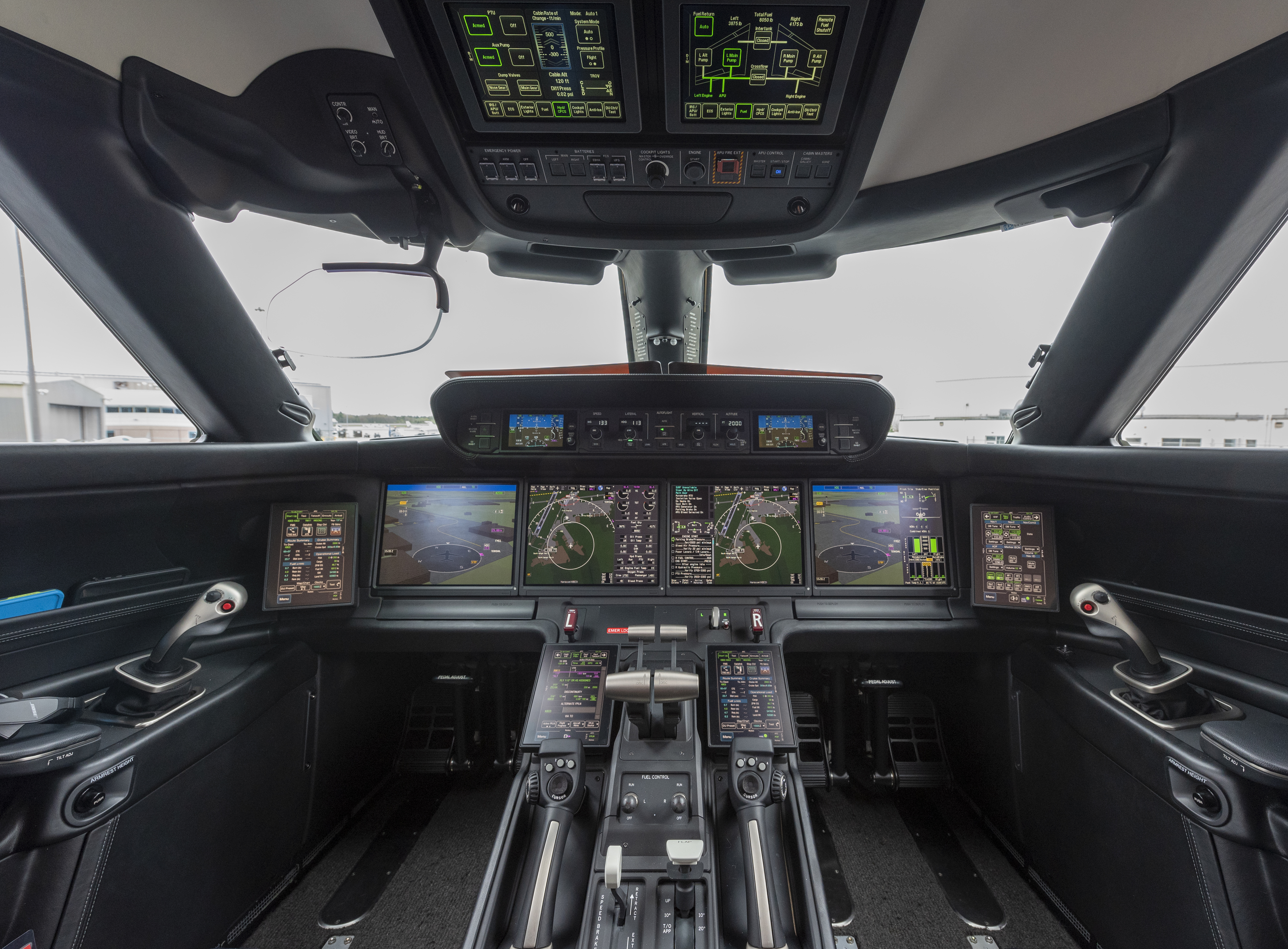
Gulfstream GVII cockpit
The first time I flew with an FMS I recoiled in horror. Information I needed was buried behind menus and it took several button presses. My last aircraft, a Gulfstream GVII, eliminates most of the buttons and now we need to press synthetic buttons on touch sensitive glass, we have to swipe left, right, up, and down, and the process of getting the automation to react is more computer programming than flying.
The "what's it doing now?" and "why is it doing that?" questions are rarely answered immediately. In an earlier automated cockpit, passing those questions on to the manufacturer often resulted in an "it can't do that" answer. These days we take videos and the manufacturer is often as stumped as we are.
Take, for example, the question of speed. In this cockpit, the commanded speed can be dialed in from a simple window. But it can just as easily come from the flight plan, the approach plate, or a series of flight control laws. While the answer is usually buried inside one of those glass screens, it can also be in a line of software the manufacturer failed to document or didn't know existed. Twenty years ago in our Gulfstream GV — high tech for its day — our commanded airspeed would go to 220 knots for apparently no reason. After a series of "it can't do that" answers from the manufacturer, we decided to live with it. We later found out that at the end of a flight plan when flying a visual pattern, if the pilot deviated from the selected altitude by 300 feet the speed would go to 220 knots on its own, perhaps a "fail safe" measure. We never found out why, but at least we could identify the cause.
Sine Qua Non
So, we in aviation are immersed in automation and there is no going back. What now? And what does that have to do with the Latin phrase, "sine qua non?" That phrase translates to "without this, nothing." It is used to denote an essential condition. In aviation, the sine qua nons are airspeed and position. You must keep the airplane at a speed that permits flight, and you must avoid the edges of the air. (The edges of the air are the land, the sea, extra terrestrial space, and any objects therein.) So how do you do that in an automated cockpit?
If things are normal, we must keep up our instrument scans to constantly monitor airspeed, altitude, and heading. If they are not right, we must investigate. If that investigation turns up empty, we are no longer in a normal situation.
If things are not normal, it may be our best interests to start throwing out automation. Airspeed not right? Decouple the autothrottles from the rest of the airplane or turn them off completely. You become the autothrottles. Altitude wrong? Turn off vertical navigation and control the pitch and power to make it right. If you are really at a loss, it might be time to assign one pilot to manually put the airplane where it needs to be while the other sorts things out.
References
(Source material)
Canadian Aviation Safety Board Engineering Report, Airbus A320, VT-EPN, dated 4 June 90
FAA Lessons Learned, Airbus A320-231, Indian Airlines Flight 605, VT-EPN, Bangalore, India, February 14, 1990, https://www.faa.gov/lessons_learned/transport_airplane/accidents/VT-EPN.
Report of the Court of Inquiry, Accident to Indian Airlines Airbus A-320 Aircraft VT-EPN on 14th February 1990 at Bangalore, Director of Airworthiness, D.G.C.A