In the early days of jet engines, turbine blade life was short and engine failures were frequent. Reducing takeoff thrust had a measurable impact on engine life but also put you closer to the end of the runway during takeoff and closer to any obstacles along your initial climb. We used to joke: "Reduced thrust: making do with less of what you didn't have enough to start with."
— James Albright

Updated:
2013-12-17
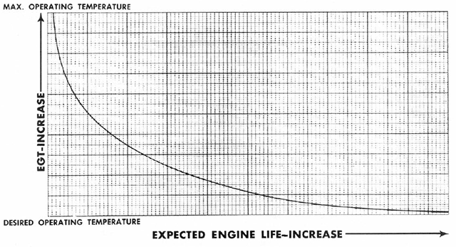
Expected Engine Life,
from 1C-135(E)C-1, Figure 7-3A.
Gulfstream pilots take note: your reduced thrust is called "Flex Thrust."
One could argue that the benefits of reducing takeoff thrust settings on a modern engine are not as significant as they used to be: engines are more reliable, are designed to operate at higher turbine temperatures, and are computer monitored and controlled. I would argue that modern engines are also much more expensive and if the manufacturer recommends you do it, you should.

1
Early rationale
- In recent years a reduced thrust take-off procedure has been developed in order to improve engine reliability and to conserve engine life. Clearly it can be used only when full take-off thrust is not required to meet the various performance requirements on the take-off and initial climb out. The object of this note is to explain the philosophy and point out the circumscribing conditions and safety precautions rather than instruct in its use in detail. Those aeroplanes approved for this procedure have Flight Manual appendices containing all the information necessary.
- A take-off can be limited by many considerations. The three which are significant in terms of reduced thrust are:
- Take-off field length.
- Take-off WAT curve (engine out climb gradients at take-off thrust).
- Net take-off flight path (engine out obstacle clearance).
- Where the proposed take-off wight is such that none of these considerations is limiting, then the take-off thrust may be reduced, within reason, until one of the considerations becomes limiting.
- There are several possible methods of applying this philosophy, but the most usual is the 'assumed temperature' method. A temperature higher than the actual OAT is determined, at which the actual take-off weight would be the Regulated Take-off weight, all other parameters having their actual values. The take-off thrust appropriate to this higher temperature is then used for the take-off. This method ensures that all the take-off performance requirements are met at the reduced thrust, with a small additional margin because the density effect of the actual take-off temperature is lower than that of the assumed temperature. While this means that, in the event of a continued take-off following engine failure the whole take=-off would be good in terms of performance, it is nevertheless recommended that full take-off power be restored in the event of an engine failure above V1.
Source: D. P. Davies, Handing the Big Jets
Increasing thrust following an engine failure may not always be in your best interest. You should also consider directional control issues, especially while still on the runway. VMCG on some aircraft, such as the B-707, can increase above V1 if thrust is increased right at V1. This should not be a factor in the G450, V1 appears to always consider V1MCG at rated thrust.
More about this: VMCG Minimum Control Speed Ground.
See also: Blade Creep.
2
Regulatory
Performance. General. (c) (c) The performance must correspond to the propulsive thrust available under the particular ambient atmospheric conditions, the particular flight condition, and the relative humidity specified in paragraph (b) of this section. The available propulsive thrust must correspond to engine power or thrust, not exceeding the approved power or thrust less—
(1) Installation losses; and
(2) The power or equivalent thrust absorbed by the accessories and services appropriate to the particular ambient atmospheric conditions and the particular flight condition.
Source: 14 CFR 25, § 25.101
The manufacturer can specify thrust settings as they deem appropriate to achieve the performance dictated by 14 CFR 25.
Controllability and Maneuverability. (h) The maneuvering capabilities in a constant speed coordinated turn at forward center of gravity, as specified in the following table, must be free of stall warning or other characteristics that might interfere with normal maneuvering:
| Configuration | Speed | Bank Angle | Thrust/power setting |
| Takeoff | V2 | 30° | Asymmetric WAT-Limited.1 |
| Takeoff | V2+XX2 | 40° | All-engines-operating climb.3 |
| En route | VFTO | 40° | Asymmetric WAT-Limited.1 |
| Landing | VREF | 40° | Symmetric for -3° flight path angle. |
1 A combination of weight, altitude, and temperature (WAT) such that the thrust or power setting produces the minimum climb gradient specified in §25.121 for the flight condition.
2 Airspeed approved for all-engines-operating initial climb.
3 That thrust or power setting which, in the event of failure of the critical engine and without any crew action to adjust the thrust or power of the remaining engines, would result in the thrust or power specified for the takeoff condition at V2, or any lesser thrust or power setting that is used for all-engines operating initial climb procedures.
Source: 14 CFR 25, § 25.143
While 14 CFR 25 does not forbid increasing power following an engine failure, it does say such a power increase should not be required.
3
Example: G450 "Flex"
Gulfstream does not advocate flex versus rated thrust for the G450 but does offer a few expanded limitations:
- FLEX takeoff thrust may be used on dry or wet, hard-surfaced runways, and the takeoff performance computed in this Appendix is limited to takeoffs for nil or uphill runway slopes and no wind or headwind conditions, only. (FLEX thrust cannot be used for takeoffs with tailwind or downhill slope; the AFM or TOLD must be used to properly compute takeoff performance for these conditions.)
- FLEX EPR takeoff thrust procedures are prohibited on runways contaminated with standing water, snow, slush, or ice. A contaminated runway is a runway where more than 25 percent of the required field length is covered by standing water or slush more than 0.125 inches (3.2 mm) deep, or that has an accumulation of snow or ice.
- Use of Wing Anti-icing bleed is not approved.
- The Anti-Skid Brake System must be ON and operating.
- The Auto Ground Spoilers must be operative when using 10° flaps for takeoff.
- All rated takeoff EPR limitations must be observed.
- To ensure that at least 75% of rated takeoff thrust is used and that takeoff configuration warnings are not inhibited, FLEX power settings must not be less than rated EPR levels provided in the FLEX tables.
- Both engines must be capable of developing rated takeoff EPR. To check for a deteriorated engine, at least one rated EPR takeoff is required every 100 flights or 100 flight hours, whichever occurs first.
- This Appendix does not include any obstacle clearance information. Check obstacle clearance using the charts presented in the Airplane Flight Manual for the selected takeoff flap setting and the assumed temperature. If obstacles are not cleared, decrease the assumed temperature by columns until obstacle clearance has been obtained. New V-speeds and FLEX EPR must then be determined.
Source: G450 Airplane Flight Manual §Appendix A §1
Those who don't flex say they don't want to give up the performance, citing the "Runway Behind You" maxim. Me? I flex whenever I can as often as I can. You are giving up a maximum of 25% of the thrust and I always ensure I have at least 2,000 feet of runway to spare. (If not, go into the runway available page of the performance computer and shorten the runway artificially, the performance computer does the rest. What if you lose an engine at V1? The data assumes you will and have a little less thrust makes directional control easier.
References
(Source material)
14 CFR 25, Title 14: Aeronautics and Space, Airworthiness Standards: Transport Category Airplanes, Federal Aviation Administration, Department of Transportation
Davies, D. P., Handling the Big Jets, Civil Aviation Authority, Kingsway, London, 1985.
Gulfstream G450 Airplane Flight Manual, Revision 35, April 18, 2013
Technical Order 1C-135(E)C-1, EC-135C Flight Manual, USAF Series, 15 February 1966
Please note: Gulfstream Aerospace Corporation has no affiliation or connection whatsoever with this website, and Gulfstream does not review, endorse, or approve any of the content included on the site. As a result, Gulfstream is not responsible or liable for your use of any materials or information obtained from this site.