Your altimeter is a marvelous piece of machinery that is highly accurate throughout almost the entire flight envelope of your aircraft. Almost, but not all. When it gets very cold, the error can be enough to lower your actual altitude well below any minimums. You, ATC, or your aircraft will have to make adjustments.
— James Albright

Updated:
2020-10-21
I've included the math here just to show there is science behind the method. But, as a pilot, what you need to know is that when it gets cold, your altimeter puts the airplane lower than it should. In most cases the error is insignificant. The colder than 0°C it is, and the higher you are than the airport's elevation, the more significant the error. You can use a set of tables, included below and in Jepps, or if your aircraft is allowed to automatically compensate, you can do that. But if you make the corrections, you need to let ATC know. They might be giving you corrected altitudes or your correction could put you in the way of aircraft that are not correcting.
1 — Altimeter temperature correction

1
Automatic Temperature Compensation (G450 Example)
These are the same tables reproduced by Jeppesen and in AIM. No matter where you get them, if you do a lot of cold weather flying you should either have the tables handy or have an aircraft that can do the math for you. (More about that below, using the Gulfstream G450 as an example.) Some aircraft can do the math because that's all it really is, math:
Note.— This chapter deals with altimeter corrections for pressure, temperature and, where appropriate, wind and terrain effects. The pilot is responsible for these corrections, except when under radar vectoring. In that case, the radar controller issues clearances such that the prescribed obstacle clearance will exist at all times, taking the cold temperature correction into account.
4.1.1 Pilot’s responsibility. The pilot-in-command is responsible for the safety of the operation and the safety of the aeroplane and of all persons on board during flight time (Annex 6, 4.5.1). This includes responsibility for obstacle clearance, except when an IFR flight is being vectored.
4.1.3 State’s responsibility. PANS-AIM, Appendix 2 (Contents of Aeronautical Information Publication), indicates that States should publish in Section GEN 3.3.5, “The criteria used to determine minimum flight altitudes”. If nothing is published, it should be assumed that no corrections have been applied by the State.
4.1.4 Air traffic control (ATC). If an aircraft is cleared by ATC to an altitude which the pilot-in-command finds unacceptable due to low temperature, then the pilot-in-command should request a higher altitude. If such a request is not received, ATC will consider that the clearance has been accepted and will be complied with. See Annex 2 and the PANS-ATM (Doc 4444), Chapter 6.
4.3.1 Requirement for temperature correction. The calculated minimum safe altitudes/heights must be adjusted when the ambient temperature on the surface is much lower than that predicted by the standard atmosphere. In such conditions, an approximate correction is 4 per cent height increase for every 10°C below standard temperature as measured at the altimeter setting source. This is safe for all altimeter setting source altitudes for temperatures above –15°C.
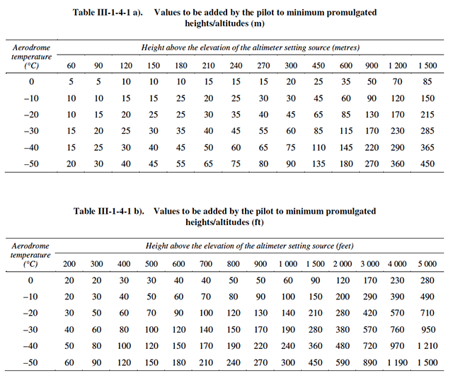
4.3.2 Tabulated corrections. For colder temperatures, a more accurate correction should be obtained from Tables III-1-4-1 a) and III-1-4-1 b). These tables are calculated for a sea level aerodrome. They are therefore conservative when applied at higher aerodromes. To calculate the corrections for specific aerodromes or altimeter setting sources above sea level, or for values not tabulated, see 4.3.3, “Corrections for specific conditions”.
Note 1.— The corrections have been rounded up to the next 5 m or 10 ft increment.
Note 2.— Temperature values from the reporting station (normally the aerodrome) nearest to the position of the aircraft should be used.
4.3.3 Corrections for specific conditions. Tables III-1-4-1 a) and III-1-4-1 b) were calculated assuming a linear variation of temperature with height. They were based on the following equation, which may be used with the appropriate value of t0, H, L0 and Hss to calculate temperature corrections for specific conditions. This equation produces results that are within 5 per cent of the accurate correction for altimeter setting sources up to 3 000 m (10 000 ft) and with minimum heights up to 1 500 m (5 000 ft) above that source.
where:
H = minimum height above the altimeter setting source (setting source is normally the aerodrome unless
otherwise specified)
t0 = taerodrome + L0 × haerodrome . . . aerodrome (or specified
temperature
reporting point) temperature adjusted to sea level
L0 = 0.0065°C per m or 0.00198°C per ft
H0 = altimeter setting source elevation
taerodrome = aerodrome (or specified temperature reporting point) temperature
haerodrome = aerodrome (or specified temperature reporting point) elevation
Source: ICAO Doc 8168 - Aircraft Operations - Vol III, Part II, Ch. 4
Note the numbers you get from this formula will not agree with the tables shown above or those in the Airman's Information Manual, which simply repeats the ICAO table. The formula is more accurate, the tables are based on a sea level airport. Using the table gives you a conservative result.
Is this correction required when flying QFE? Yes. Note that the PANS OPS extract above doesn't mention QNH or QFE, it is implied because they are dealing with heights. Logically you are worried about heights above the terrain, which concerns QNH and QFE in cold temperatures.
2
U.S. procedures
a. PILOTS MUST NOT MAKE AN ALTIMETER CHANGE to accomplish an altitude correction. Pilots must ensure that the altimeter is set to the current altimeter setting provided by ATC in accordance with 14 CFR §91.121.
b. Actions on when and where to make corrections: Pilots will make an altitude correction to the published, “at”, “at or above”, and “at or below” altitudes on all designated segment(s) to all runways for all published instrument approach procedures when the reported airport temperature is at or below the published CTA temperature on the approach plate. A pilot may request an altitude correction (if desired) on any approach at any United States airport when extreme cold temperature is encountered. Pilots making a correction must comply with ATC reporting requirements.
c. Correctable altitudes: ATC does not apply a cold temperature correction to their Minimum Vectoring Altitude (MVA) or Minimum IFR Altitude (MIA) charts. Pilots must request approval from ATC to apply a cold temperature correction to any ATC assigned altitude. Pilots must not correct altitudes published on Standard Instrument Departures (SIDs), Obstacle Departure Procedures (ODPs), and Standard Terminal Arrivals (STARs).
d. Use of corrected MDA/DA: Pilots will use the corrected MDA or DA as the minimum altitude for an approach. Pilots must meet the requirements in 14 CFR Part 91.175 in order to operate below the corrected MDA or DA. Pilots must see and avoid" "obstacles when descending below the minimum altitude on the approach.
NOTE−The corrected DA or MDA does not affect the visibility minima published for the approach. With the application of a cold temperature correction to the DA or MDA, the airplane should be in a position on the glideslope/glide- path or at the published missed approach point to identify the runway environment.
e. How to apply Cold Temperature Altitude Corrections on an Approach.
1. All Segments Method: Pilots may correct all segment altitudes from the initial approach fix (IAF) altitude to the missed approach (MA) final holding altitude. Pilots familiar with the information in this section and the procedures for accomplishing the all segments method, only need to use the published “snowflake” icon, /CTA temperature limit on the approach chart for making corrections. Pilots are not required to reference the CTA list. The altitude correction is calculated as follows:
(a) Manual correction: Pilots will make a manual correction when the aircraft is not equipped with a temperature compensating system or when a compensating system is not used to make the correction. Use TBL 7−3−1, ICAO Cold Temperature Error Table to calculate the correction needed for the approach segment(s).
(1) Correct all altitudes from the final approach fix (FAF)/PFAF up to and including the IAF altitude: Calculate the correction by taking the FAF/PFAF altitude and subtracting the airport elevation. Use this number to enter the height above airport column in TBL 7−3−1 until reaching the reported temperature from the “Reported Temperature” row. Round this number as applicable and then add to all altitudes from the FAF altitude through the IAF altitude.
(2) Correct all altitudes in the final segment: Calculate the correction by taking the MDA or DA for the approach being flown and subtract the airport elevation. Use this number to enter the height above airport column in TBL 7−3−1 until reaching the reported temperature from the “Reported Temperature” row. Use this number or round up to next nearest 100. Add this number to MDA or DA, as applicable, and any applicable step−down fixes in the final segment.
(3) Correct final holding altitude in the MA Segment: Calculate the correction by taking the final missed approach (MA) holding altitude and subtract the airport elevation. Use this number to enter the height above airport column in TBL 7−3−1 until reaching the reported temperature from the “Report- ed Temperature” row. Round this number as applicable and then add to the final MA altitude only.
(b) Aircraft with temperature compensating systems: If flying an aircraft equipped with a system capable of temperature compensation, follow the instructions for applying temperature compensation provided in the airplane flight manual (AFM), AFM supplement, or system operating manual. Ensure that temperature compensation system is on and active prior to the IAF and remains active throughout the entire approach and missed approach.
(1) Pilots that have a system that is able to calculate a temperature−corrected DA or MDA may use the system for this purpose.
(2) Pilots that have a system unable to calculate a temperature corrected DA or MDA will manually calculate an altitude correction for the MDA or DA.
NOTE−Some systems apply temperature compensation only to those altitudes associated with an instrument approach procedure loaded into the active flight plan while other systems apply temperature compensation to all procedure altitudes or user entered altitudes in the active flight plan, including altitudes associated with a STAR. For those systems that apply temperature compensation to all altitudes in the active flight plan, delay activating temperature compensation until the aircraft has passed the last altitude constraint associated with the active STAR.
2. Individual Segment(s) Method: Pilots are allowed to correct only the marked segment(s) indicated in the CTA list. https://www.faa.gov/ air_traffic/flight_info/aeronav/digital_products/dtpp/search/. Pilots using the Individual Segment(s) Method will reference the CTA list to determine which segment(s) need a correction. See FIG 7−3−1.
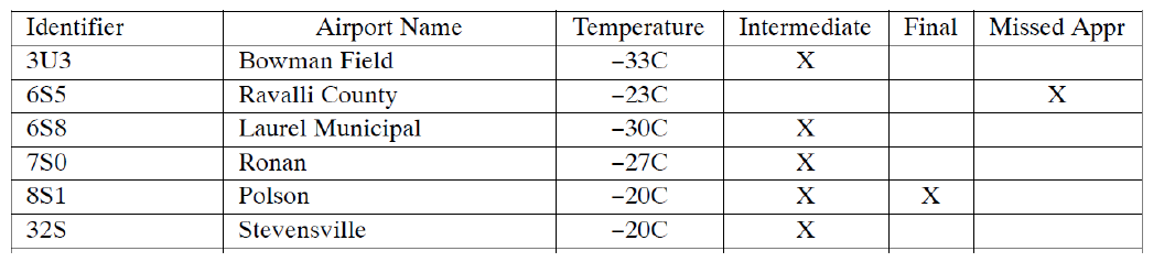
AIM, fig. 7-3-1.
(a) Manual Correction: Pilots will make a manual correction when the aircraft is not equipped with a temperature compensating system or when a compensating system is not used to make the correction. Use TBL 7−3−1, ICAO Cold Temperature Error Table, to calculate the correction needed for the approach segment(s).v(1) Intermediate Segment: All altitudes from the FAF/PFAF up to but not including the intermediate fix (IF) altitude. Calculate the correction by taking FAF/PFAF altitude and subtracting the airport elevation. Use this number to enter the height above airport column in TBL 7−3−1 until reaching the reported temperature from the “Reported Temperature” row. Round this number as applicable and then add to FAF altitude and all step−down" "altitudes within the intermediate segment (inside of the waypoint labeled “(IF)”).
(2) Final segment: Calculate correction by taking the MDA or DA for the approach flown and subtract the airport elevation. Use this number to enter the height above airport column in TBL 7−3−1 until reaching the reported temperature from the “Reported Temperature” row. Use this number or round up to next nearest 100. Add this number to MDA or DA, as applicable, and any applicable step−down fixes in the final segment.
(3) Missed Approach Segment: Calculate the correction by taking the final MA holding altitude and subtract the airport elevation. Use this number to enter the height above airport column in TBL 7−3−1 until reaching the reported temperature from the “Reported Temperature” row. Round this number as applicable and then add to the final MA altitude only.
(b) Aircraft with temperature compensating system: If flying an aircraft equipped with a system capable of temperature compensation, follow the instructions for applying temperature compensation provided in the AFM, AFM supplement, or system operating manual. Ensure the temperature compensation system is on and active prior to the segment(s) being corrected. Manually calculate an altimetry correction for the MDA or DA. Determine an altimetry correction from the ICAO table based on the reported airport temperature and the height difference between the MDA or DA, as applicable, and the airport elevation, or use the compensating system to calculate a temperature corrected altitude for the published MDA or DA if able.
f. Acceptable Use of Table for manual CTA altitude correction: (See TBL 7−3−1.) Pilots may calculate a correction with a visual interpolation of the chart when using reported temperature and height above airport. This calculated altitude correction may then be rounded to the nearest whole hundred or rounded up. For example, a correction of 130 ft. from the chart may be rounded to 100 ft. or 200 ft. A correction of 280 ft. will be rounded up to 300 ft. This rounded correction will be added to the appropriate altitudes for the “Individual” or “All” segment method. The correction calculated from the table for the MDA or DA may be used as is or rounded up, but never rounded down. This number will be added to the MDA, DA, and all step−down fixes inside of the FAF as applicable.
1. No extrapolation above the 5000 ft. column is required. Pilots may use the 5000 ft. “height above airport in feet” column for calculating corrections when the calculated altitude is greater than 5000 ft. above reporting station elevation. Pilots must add the correction(s) from the table to the affected segment altitude(s) and fly at the new corrected altitude. Do not round down when using the 5000 ft. column for calculated height above airport values greater than 5000 ft. Pilots may extrapolate above the 5000 ft. column to apply a correction if desired.
2. These techniques have been adopted to minimize pilot distraction by limiting the number of entries into the table when making corrections." "Although not all altitudes on the approach will be corrected back to standard day values, a safe distance above the terrain/obstacle will be maintained on the corrected approach segment(s). Pilots may calculate a correction for each fix based on the fix altitude if desired.
NOTE−Pilots may use Real Time Mesoscale Analysis (RTMA): Alternate Report of Surface Temperature, for computing altitude corrections, when airport temperatures are not available via normal reporting. The RTMA website is http://nomads.ncep.noaa.gov/pub/data/nccf/com/rtma/ prod/airport_temps/.
g. Communication: Pilots must request approval from ATC whenever applying a cold temperature altitude correction. Pilots do not need to inform ATC of the final approach segment correction (i.e., new MDA or DA). This request should be made on initial radio contact with the ATC facility issuing the approach clearance. ATC requires this information in order to ensure appropriate vertical separation between known traffic. Pilots should query ATC when vectored altitudes to a segment are lower than the requested corrected altitude. Pilots are encouraged to self−announce corrected altitude when flying into a non−towered airfield.
1. The following are examples of appropriate pilot−to−ATC communication when applying cold− temperature altitude corrections.
(a) On initial check−in with ATC providing approach clearance: Missoula, MT (example below).
• Vectors to final approach course: Outside of IAFs: “Request 9700 ft. for cold temperature operations.”
• Vectors to final approach course: Inside of ODIRE: “Request 7300 ft. for cold temperature operations.”
• Missed Approach segment: “Require final holding altitude, 12500 ft. on missed approach for cold temperature operations.”
(b) Pilots cleared by ATC for an instrument approach procedure; “Cleared the RNAV (GPS) Y RWY 12 approach (from any IAF)”. Missoula, MT (example below).
• IAF: “Request 9700 ft. for cold temperature operations at LANNY, CHARL, or ODIRE.”
Source: AIM, §7-3-5
Example
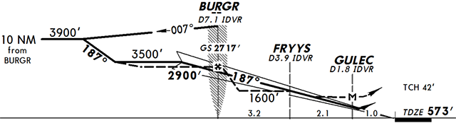
JeppView, pg. KLEB 11-1
Flying into Lebanon, New Hampshire on the ILS Rwy 18 the ATIS reports the surface temperature is -10°C and you have been vectored to intercept the ILS at 3500 feet. What should you do?
This altitude is 3,000 feet above the altimeter setting source so, using the correction table, you need to add 290 feet to your indicated altitude. You should request to fly the intercept at 3,800 feet indicated altitude, then check your glide slope crossing at 2,930 feet and the minimum stepdown at 1,700'.
Notice that this correction, in accordance with the U.S. Cold Temperature Restricted Airports list is not mandatory at Lebanon, New Hampshire until -20°C and even then only on the intermediate and final approach segments. You can apply it, but regardless of the temperature you need to inform ATC that you are doing so. (See U.S. Procedures for more about this.)
3
Flight Path Angle (FPA) corrections (don't!)
In 2015 there was a crash of an Air Canada Airbus where the crew employed a company sanctioned procedure to increase their Flight Path Angle (FPA) to compensate for their increased Final Approach Fix altitude, which was temperature compensated. Flying the charted FPA from the higher indicated altitude at the FAF would result in arriving over the runway at too high an altitude. In theory, computing a higher FPA based on the expected indicated altitudes would get them over the threshold at the correct height. The problem with this theory is that the corrected FPA needs to be constantly updated. Airbus has since abandoned this procedure. If you've picked it up somewhere, you also need to abandon the procedure. Fly the charted FPA, even when using temperature compensated altitudes.
More about this — Case Study: Air Canada 624.
The problem with adjusting your FPA to make up for a higher temperature compensated altitude at the FAF is that the temperature compensation decreases as you descend. If you increase your angle based on the 2,000 foot correction, you will have too much angle as you descend.
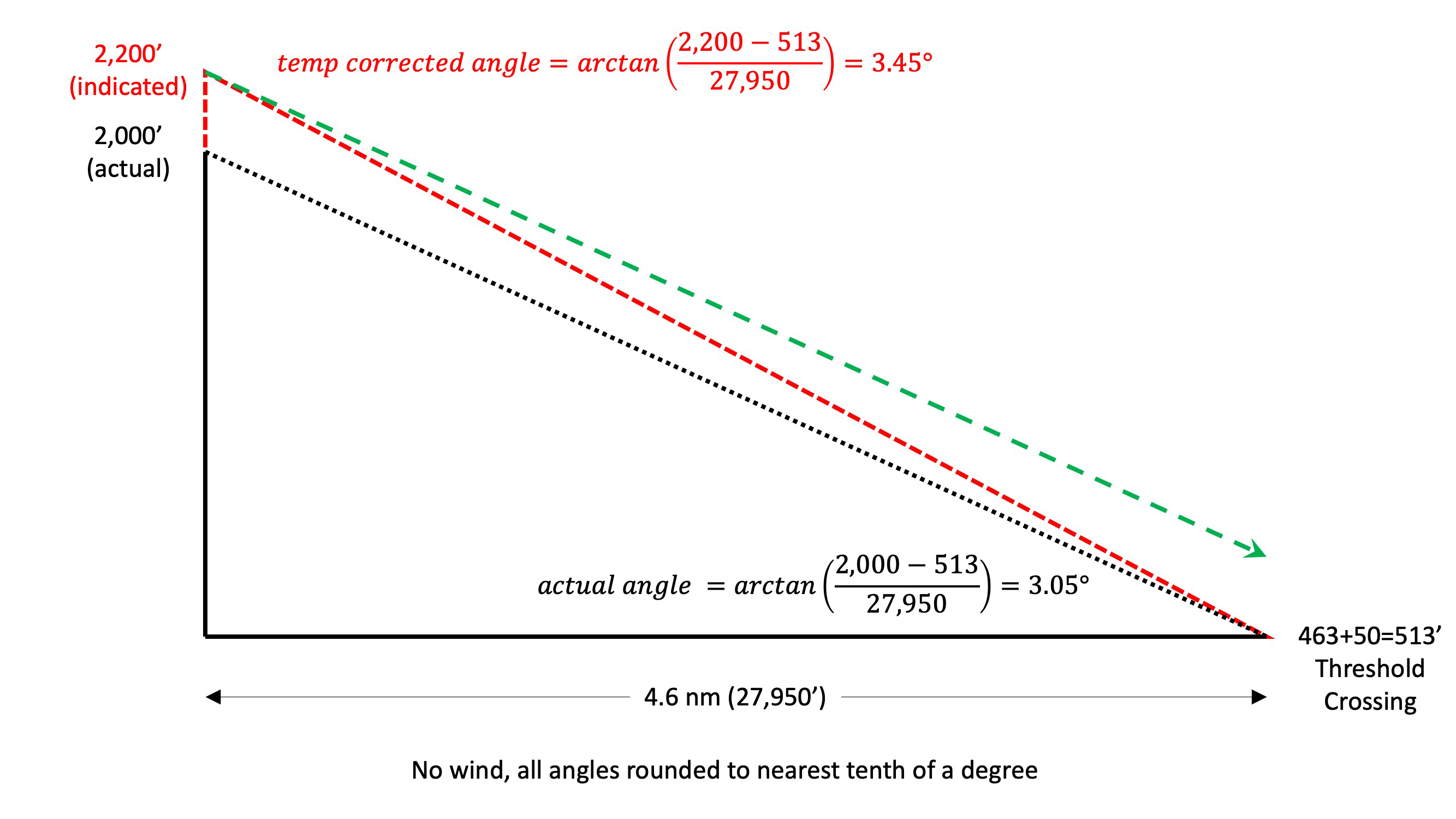
In the case of Air Canada 624, company procedures had the pilots correct the altitude at the FAF, rounding up to the next even 100 feet. So they began the approach at 2,200 feet. Company rules also had them fly an increased FPA, using 3.5 degrees instead of the published 3.08 degrees. For the sake of the math, we will use the computed value of 3.45, making this a conservative examination.
Doing the math, without temperature compensation the required FPA to cross the threshold at 50 feet would have been 3.05 degrees. Flying this angle from the FAF's temperature compensated altitude (the green dashed line) would have left them too high. In theory, the temperature compensated 3.5 degree FPA would get them to the threshold at 50 feet (the red dotted line).
FPA math, initial assumptions
But that increased FPA is only valid at the higher altitude. You can visualize the problem by recomputing everything 1 nm after the FAF. The aircraft descended from 2,000 feet at 3.45 degrees and ended up 107 feet lower than predicted. Had the crew recomputed a new corrected FPA, they would have shallowed their descent rate to 3.29 degrees. So they were now 0.16 degrees too steep.

FPA math
Repeating this process at 2 nm shows them to be 134 feet lower than predicted and the error in their FPA is a little higher.
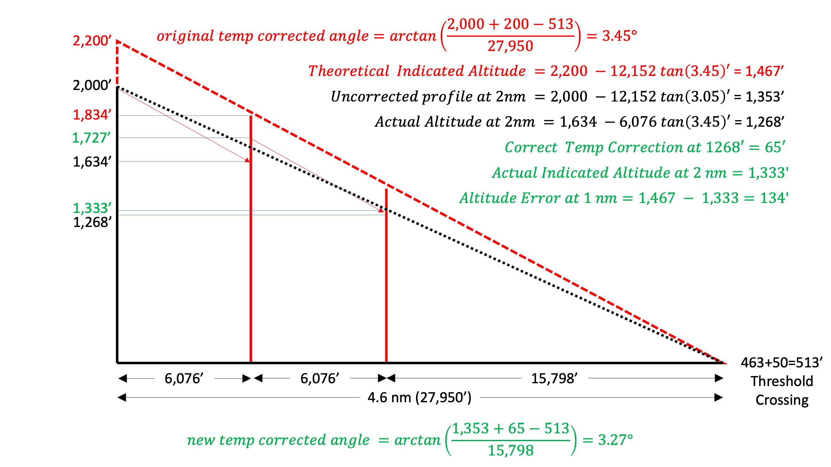
More FPA math
At 3 nm the errors increase.

More FPA math
At 4 nm the airplane is 194 feet too low.
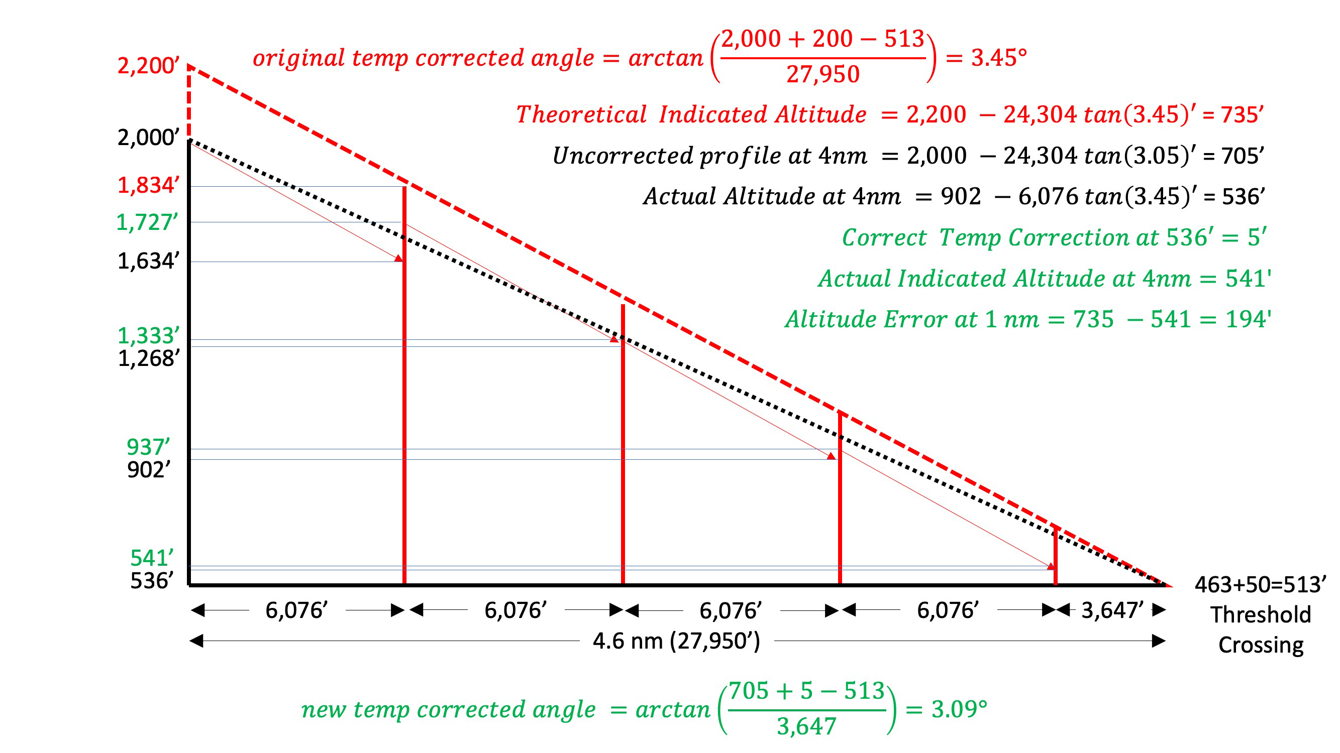
More FPA math
The temperature corrected FPA did not cause the crash, the crew should never have continued the approach below the MDA without the correct visual cues in sight. But the steeper approach set them up for the visual illusions that got them in the end. They should have tracked their distance to the runway as provided in their SOPs. For more about how to avoid this FPA error and the visual illusion, see: Sitting Duck.
4
Automatic temperature compensation (G450 example)
G450 aircraft with ASC 059 can automatically modify waypoint constraint altitudes to compensate for the effects of hot or cold weather.
Temperature compensation is calculated when a landing temperature is entered by the pilot (on the LAND/GA INIT page) and a valid runway elevation is present.
Source: G450 Aircraft Operating Manual, §2B-26-80 ¶3.A.
Temperature Compensation Configuration
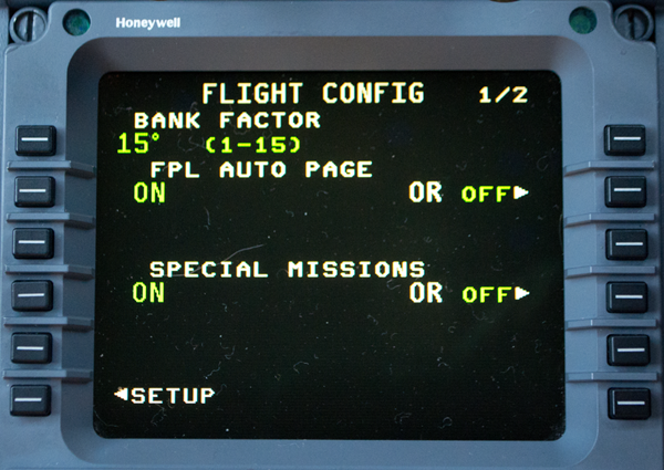
Flight Config 1/2
The first step in the temperature compensation activation procedure is to configure the desired temperature compensation. Temperature compensation configuration is performed on the TEMP COMP CONFIG page. The TEMP COMP CONFIG page is accessed from the FLIGHT CONFIG page 2.
Source: G450 Aircraft Operating Manual, §2B-26-80 ¶3.A.
Flight Config 1/2
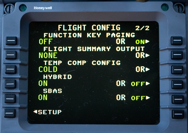
Pushing LSK 3R on the FLIGHT CONFIG page 2 displays the TEMP COMP CONFIG page.
Temperature compensation is configured by selecting the desired temperature compensation mode. Temperature compensation is calculated when the entered landing temperature is valid for the selected temperature compensation mode (COLD or HOT & COLD) and an approach procedure is selected and activated. The compensation modes displayed on the TEMP COMP CONFIG page are as follows
- OFF (LSK 1L) - Selecting OFF turns the temperature compensation off.
- COLD (LSK 2L) - Pushing LSK 2L selects the COLD temperature compensation mode. For COLD temperature compensation, the entered temperature range for the arrival airport elevation must be between --55°C and 0°C
- HOT & COLD (LSK 3L) - Pushing LSK 3L selects the HOT & COLD temperature compensation mode. For HOT & COLD temperature compensation, the entered temperature range for the arrival airport elevation must be from --55°C to + 55° C.
Source: G450 Aircraft Operating Manual, §2B-26-80 ¶3.A.
Set this to COLD and keep it there. Nobody uses HOT and hardly anyone uses COLD. But with this set to COLD you will have the option of using it whenever your temperature is below 0°C.
Approach Selection and Activation
After the desired temperature compensation configuration is selected, an approach must be selected and activated in the active flight plan.
Source: G450 Aircraft Operating Manual, §2B-26-80 §3.B.
Landing Surface Temperature Entry
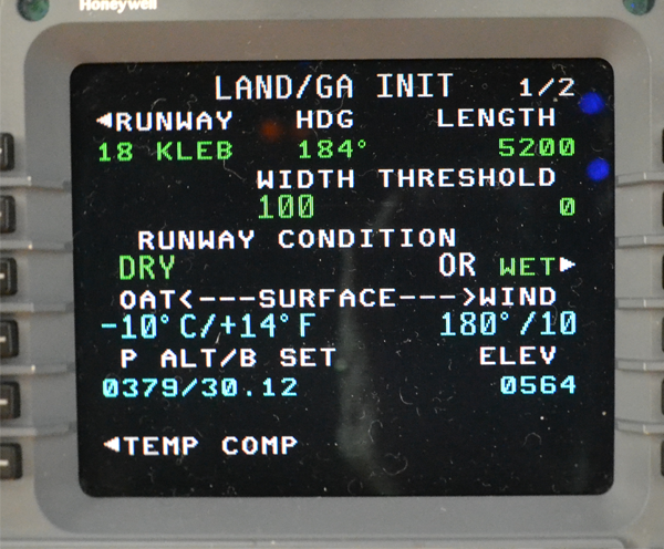
LAND/GA INIT page
The landing surface temperature is entered on the LAND/GA INIT page 1. The LAND/GA INIT page is accessed by selecting the LANDING prompt (LSK 6R) on the ARRIVAL page or the LANDING prompt (LSK 4R) on the PERF INDEX page. Landing surface temperature is entered by entering the temperature value into the scratchpad and pushing LSK 4L on the LAND/GA INIT page 1.
The TEMP COMP prompt is displayed adjacent to LSK 6L when the landing surface temperature is entered. Selecting the TEMP COMP prompt (LSK 6L) on the LAND/GA INIT page displays the TEMP COMP page 1.
Source: G450 Aircraft Operating Manual, §2B-26-80 §3.C.
Temperature Compensation Verification and Activation
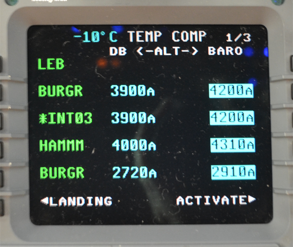
TEMP COMP page
Verification and activation of temperature compensation for the approach/missed approach waypoint crossing altitudes is performed on the TEMP COMP pages. The TEMP COMP pages are accessed by pushing LSK 6L on the LAND/GA INIT page 1. The TEMP COMP pages are also accessed by selecting TEMP COMP prompt (when it is displayed) on the ACTIVE FLT PLAN page.
The left column lists the names of the waypoints in the flight plan. The middle column lists the database altitude constraints corresponding to the waypoints. The right column lists the corresponding temperature compensated altitude values. If a waypoint does not have a navigation database altitude constraint, the database altitude and baro-corrected altitude fields are blank. Pushing LSK 6R activates temperature compensation. Once temperature compensation has been activated, the prompt at LSK 6R changes to CANCEL. Selecting CANCEL turns off temperature compensation. The final entry on the last TEMP COMP page permits the flight crew to manually enter the appropriate MDA/DA. When the appropriate MDA/DA is entered by the flight crew, the temperature-corrected altitude is displayed. The flight crew uses this temperature-corrected altitude for input on the Display Controller and Flight Guidance Panel.
Source: G450 Aircraft Operating Manual, §2B-26-80 §3.D.
Temperature Compensated Altitude Constraint Display
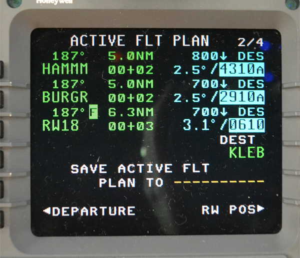
TEMP COMP page,
Once temperature compensation is activated, the temperature compensated altitude constraints are displayed on the ACTIVE FLT PLAN pages.
Temperature compensated altitudes from the NDB are displayed in reverse video on the ACTIVE FLT PLAN pages for pilot awareness. Angle constraints, such as the runway waypoint, are displayed as uncompensated values on the ACTIVE FLT PLAN pages for consistency with the NDB and approach charts. Pushing LSK 6R on an ACTIVE FLT PLAN page when temperature compensation is activated, displays the TEMP COMP page. If the landing surface temperature is deleted after the landing surface temperature is entered and temperature compensation is activated, the temperature compensation is canceled and the message TEMP COMP CANCELED is displayed in the scratchpad. The message is not displayed if the landing temperature is deleted prior to activating temperature compensation. If temperature compensation has been activated and then another landing temperature is entered which is outside the valid temperature range, the entry is not accepted and the temperature compensation is not changed.
Source: G450 Aircraft Operating Manual, §2B-26-80 §3.E.
References
(Source material)
Aeronautical Information Manual
Gulfstream G450 Aircraft Operating Manual, Revision 35, April 30, 2013.
Gulfstream G450 Aircraft Service Change Number 059B, Enhanced Navigation, December 22, 2011
Honeywell Direct-To Temperature Compensation, Nov 2013, Feb 2014, and Mar 2014
ICAO Doc 8168 - Aircraft Operations - Vol III - Flight Procedures, Procedures for Air Navigation Services, International Civil Aviation Organization, First Edition, 2018
Please note: Gulfstream Aerospace Corporation has no affiliation or connection whatsoever with this website, and Gulfstream does not review, endorse, or approve any of the content included on the site. As a result, Gulfstream is not responsible or liable for your use of any materials or information obtained from this site.