When you graduated from small airplanes to large, you also graduated from low inertia to high. What? Larger mass means once things start going in a certain direction and speed, it is harder to change that. (An object in motion tends to . . . See: Mechanics.)
— James Albright

Updated:
2025-10-01
In small aircraft you could easily overcome a bit of wind gust with a lot of throttle. In larger airplanes, you need to add to your approach speed because the relative impact of throttle becomes smaller as the aircraft becomes larger. (Plus we also have spool up time, etc.) We are often told that on approach we are flying at 1.3 times the stall speed, so the margins are "huge." Not really.
4 — Lose or keep the additive?
There are a lot of variables here, such as how quickly is the wind gusting? If you decide to pull the throttles at 100 feet, what happens if the wind speed is low and gusting higher? Or high and gusting lower? Rather than tackle all the variables, let's look at a hypothetical situation and apply three techniques: no additive, an additive which we get rid of at 100 feet, or an additive we keep until the runway threshold.
We don’t need to be afraid of the wind nor do we have to trust it will behave as we expect. We can simply allow for the wind to misbehave and plan our approach speed accordingly. On a gusty wind day, flying an approach speed without a wind additive risks running out of flying speed prior to the landing flare. Your only options may be to add to your approach speed or to divert. An additive may be required, recommended, forbidden, or not mentioned at all. I recommend you research your manuals, see what flexibility you have, and fly the additives if you can. If the resulting landing distance or threat of running out of speed are too great, find another place to land.

1
History
Someone thought of this . . .
I like to say that in the world of jets, "In the beginning there was the Boeing 707 . . ."
From the Boeing 707, circa 1961
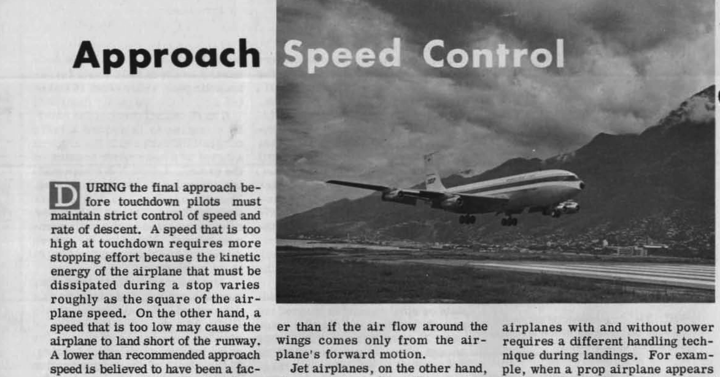
April 1961 issue of Boeing Airliner
- During the final approach before touchdown pilots must maintain strict control of speed and rate of descent. A speed that is too high at touchdown requires more stopping effort because the kinetic energy of the airplane that must be dissipated during a stop varies roughly as the square of the airplane speed. On the other hand, a speed that is too low may cause the airplane to land short of the runway.
- Basic differences between jet and prop-powered airplanes in their response to power applications at low speeds appear to remain a problem, particularly with new pilots and their limited experience in jets.
- ...prop airplanes have two stalling speeds — one with power off and a lower one with power on. This difference in stalling speeds is due to the slipstream effect from the props around the wings.
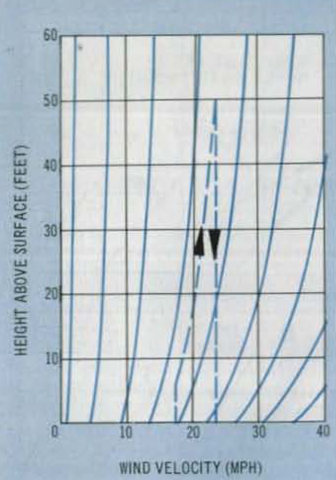
Boeing Airliner, figure 2
For years pilots have known that winds tend to decrease in velocity near the ground. The extent of this wind-velocity gradient is generally known to be similar to the curves shown in Fig. 3. Studies indicate that the greatest changes in wind velocity occur between 300 feet and the earth's surface. Most of the information on wind gradients, as shown in Fig. 3, pertain only to winds over grassy and otherwise unobstructed terrain. It is known, however, that wind gradients can be affected by terrain contours, wind velocities at altitude, the temperature lapse rate, and convective influences due to heating or cooling of the surface. Although wind velocities at various heights above the ground are difficult to predict, wind direction remains fairly constant below the 300-foot level.
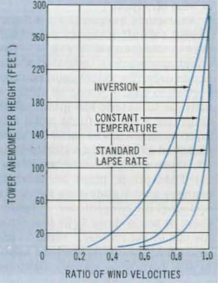
Boeing Airliner, figure 3
At least one of the short landings reported during 707 operations has been laid to a sudden drop off in headwind velocity coupled with a lower than recommended approach airspeed before touchdown.
Following the analysis of wind gradient effects on approaches and landing, a change to the 707 Pilot Training Manual (Document 00-3529) has been recommended calling for an increase in the indicated airspeed to be used during approach. Due to the lack of definitive information on a wind gradient as it might exist at a destination airport, the following rule of thumb is being incorporated in the Pilot Training Manual to partially compensate for wind gradient effect:
One-half of the tower reported wind velocity should be added to the VREF on the approach to obtain the target speed. During this approach procedure, the airspeed bug should be left at the Vref for the particular gross weight. As the airplane descends to the runway some bleed off in airspeed should be expected.
As noted below the 1/2 VWINSD addition should not exceed 20 knots. The curves in Fig. 3 indicate that a considerable wind gradient can be expected under certain conditions.
Gustiness must also be considered. Theoretically at least, gust effects should be added to any wind gradient correction. However, because the pilot can partially compensate with power and elevator control and some margins are already built into the 1.3 VS reference speed recommended for approaches, the total speed correction added to the 1.3 VS should not be more than 20 knots (maximum for combined gust and wind gradient corrections). Theoretically, the incremental approach speed increase due to gradient and gustiness approaches zero for the 90 degree crosswind. However, gustiness should still call for a speed increase over Vref because of the possible directional shifts in the gusts. To cover both of these theoretical considerations, the following paragraph Is being added to the Pilot Training Manual:
"The full value of the gusts should be added to VREF. In addition to the allowance for the wind gradient effect, except that the total velocity increment for both gusts and gradient need not exceed 20 knots. In the case of crosswinds, the component of wind down the runway only need be considered for gradient allowance; however, the full gust allowance should still apply regardless of wind direction."
So Boeing has given us the "half the steady and all the gust up to twenty" idea. But they have since changed that:
- Customers requested Boeing’s assistance with landing distance & approach speeds.
- Procedural wind additives (1/2 the steady state and all the gust, min 5 knots, max of 20 knots) rendered an opportunity that could immediately help most Boeing models.
- Boeing 20 knot wind additive dates back to the 707!
- What’s changed?
- We now have predictive and reactive windshear systems on our airplanes
- Weather and winds are measured and reported much more accurately at most airports, and available on our flight displays
- Engine spool-up times have dramatically reduced. Airplanes react much quicker to thrust application
- Airspeed indicators are much more precise, allowing control to within 1 knot, vs 5 knots
- Pilots now trained to fly approach speed all the way to flare, rather than allow it to bleed off with change in wind gradient
- Boeing analysis and piloted simulation study supports reduction of the maximum approach speed wind additive from +20 knots to +15 knots. Applies to normal & non-normal operations.
- Flight Crew Training Manual will be updated in the June 2018 Revision to reflect the new 15 knot maximum wind additive change.
Source: Cross-model Wind Additive Reduction Study
2
Stall margins
Reference Speed
If you are flying a transport category aircraft, your approach speed cannot be lower than reference speed, VREF, which may not be lower than 1.23 times the reference stall speed in the landing configuration, VSR. Furthermore, 14 CFR 25.143 further specifies that when landing, the aircraft must be maneuverable and free of stall warning or other characteristics that might interfere with normal maneuvering up to 40° of bank with symmetric thrust while flying a -3° flight path angle. While we all think of stalls as occurring at certain airspeeds, we know that a stall actually happens at particular angles of attack, what an aeronautical engineer calls the “alpha.”
(a) The horizontal distance necessary to land and to come to a complete stop (or to a speed of approximately 3 knots for water landings) from a point 50 feet above the landing surface must be determined (for standard temperatures, at each weight altitude, and wind within the operational limits established by the applicant for the airplane):
(1) In non-icing conditions; and
(2) In icing conditions with the most critical of the landing ice accretion(s) defined in Appendices C and O of this part, as applicable, in accordance with §25.21(g), if VREF for icing conditions exceeds VREF for non-icing conditions by more than 5 knots CAS at the maximum landing weight.
(b) In determining the distance in paragraph (a) of this section:
(1) The airplane must be in the landing configuration.
(2) A stabilized approach, with a calibrated airspeed of not less than VREF, must be maintained down to the 50-foot height.
(i) In non-icing conditions, VREF may not be less than:
(A) 1.23 VSR0;
(B) VMCL established under §25.149(f); and
(C) A speed that provides the maneuvering capability specified in §25.143(h).
Source: 14 CFR 25, §25.125, Landing.
(h) The maneuvering capabilities in a constant speed coordinated turn at forward center of gravity, as specified in the following table, must be free of stall warning or other characteristics that might interfere with normal maneuvering:
| Configuration | Speed | Maneuvering bank angle in a coordinated turn | Thrust/power setting |
| Takeoff | V2 | 30° | Asymmetric WAT-Limited.1 |
| Takeoff | 2V2+XX | 40° | All-engines-operating climb.3 |
| En route | VFTO | 40° | Asymmetric WAT-Limited.1 |
| Landing | VREF | 40° | Symmetric for -3° flight path angle. |
1A combination of weight, altitude, and temperature (WAT) such that the thrust or power setting produces the minimum climb gradient specified in §25.121 for the flight condition.
2Airspeed approved for all-engines-operating initial climb.
3That thrust or power setting which, in the event of failure of the critical engine and without any crew action to adjust the thrust or power of the remaining engines, would result in the thrust or power specified for the takeoff condition at V2, or any lesser thrust or power setting that is used for all-engines-operating initial climb procedures.
Source: 14 CFR 25, §25.143, General.
g Loading
We all know that a 60° bank turn in level flight requires 2 g's, the math behind that is:
Since the maneuvering capability for landing requires being able to execute a coordinated turn at 40° of bank during a 3° flight path angle with out stall warning. That requires:
(j) For flight in icing conditions before the ice protection system has been activated and is performing its intended function, it must be demonstrated in flight with the most critical of the ice accretion(s) defined in Appendix C, part II, paragraph (e) of this part and Appendix O, part II, paragraph (d) of this part, as applicable, in accordance with §25.21(g), that:
(1) The airplane is controllable in a pull-up maneuver up to 1.5 g load factor;
It may seem odd that this only refers to flight in icing conditions, but there are other sections that also reference 1.5 g.
(f) The stall warning margin must be sufficient in both non-icing and icing conditions to allow the pilot to prevent stalling when the pilot starts a recovery maneuver not less than one second after the onset of stall warning in slow-down turns with at least 1.5 g load factor normal to the flight path and airspeed deceleration rates of at least 2 knots per second. When demonstrating compliance with this paragraph for icing conditions, the pilot must perform the recovery maneuver in the same way as for the airplane in non-icing conditions.
Source: 14 CFR 25, §25.207, Stall warning.
(d) The airplane must be designed for a maneuvering load factor of 1.5 g at the maximum take-off weight with the wing flaps and similar high lift devices in the landing configurations.
Source: 14 CFR 25, §25.345, High lift devices.
Normalized AOA
Most of us learn early on that the angle of attack is the angular difference between the chord line of the wing and the relative wind of the aircraft cutting through the air. That isn't precisely correct, but it is close enough. We can change the effective chord line of the wing with leading and trailing edge devices, such as slats and flaps. The shape of the aircraft itself may create lift and the angle upon which the wing is mounted versus the reference provided to you on your attitude indicator, the “angle of incidence,” will also alter the wing’s angle of attack to your perceived angle of attack. But for we pilots, thinking of AOA as a function of the relative wind and the wing is good enough.
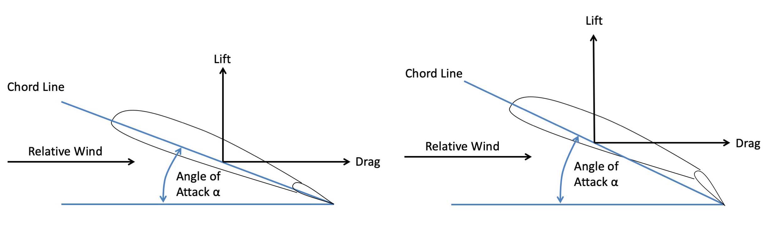
AOA with and without flaps
Left unsaid is that an angle is something you measure in units, usually degrees. It is a number, such as 15 degrees. We also learn that the wing stalls at a particular AOA. Here again that is given in degrees, such as "the wing stalls at 18 degrees angle of attack." As pilots, we don’t use AOA measured in degrees because that measurement varies too much with flight condition and aircraft configuration.
More about this: Angle of Attack.
Airplanes that do display "AOA" are usually showing us "Normalized" AOA. That is just a fancy way of saying they are giving you a ratio of the actual AOA (in degrees) divided by the stall reference AOA (in degrees) to give you a number between 0.00 and around 1.00. Yes, the number can actually exceed 1.00 as the wing still produces usable lift, but for us pilots, thinking of 1.00 as our upper limit helps our understanding of the concepts. The maximum allowable isn’t necessarily the maximum achievable. A fly-by-wire airplane may use a lower AOA to prevent overshoots. An airplane with a conventional stick pusher may do the same to ensure the system activates early enough. In either case, your avionics do the math for you, but a common formula for Normalized AOA (NAOA) is:
Where each AOA term is measured in units of degrees, the resulting NAOA is a ratio and has no units. We typically think of 1.00 NAOA as the stall angle of attack but the real value is usually a bit higher, an example could be 1.06 for the stall reference angle of attack and 1.10 where the wing actually stalls. While far from universal, most aircraft in my logbook flew final approach at NAOA around 0.60 and would give you a stall warning (limiter, stick shaker, or pusher) between NAOA = 0.85 and 0.97.
Here is NAOA (labeled AOA) shown on my airplane just above minimums on a day where our VAPP was VREF+13, because the winds were at 8 knots gusting to 17 knots and we added half the steady state winds (4) and all of the gust (9).
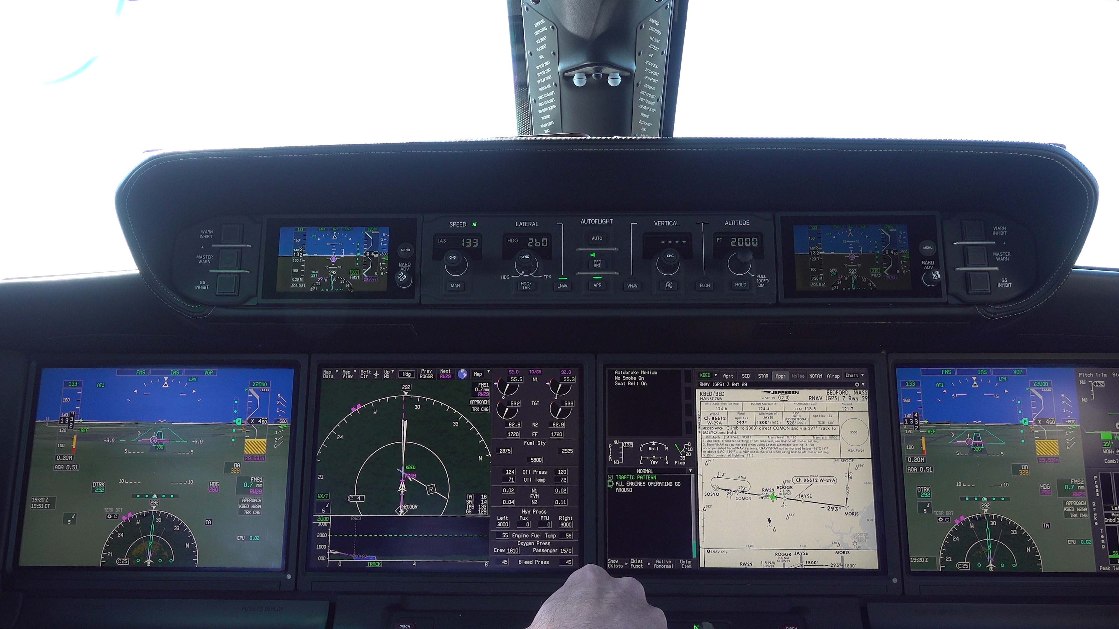
Normalized Angle of Attack (below airspeed tape)
Theory versus reality
We often talk academically about AOA as if it were an instrument that got set somehow: you establish the thrust and pitch, the AOA goes to the correct value and stays there. It doesn't work that way. Even with calm winds there is a substantial lag time between setting the aircraft control parameters and expecting to see the result on your performance indicator. Here is an example on a gusty wind day where we were flying at VREF + 13 to account for winds at 8 knots gusting to 17. You can scroll to the 11 minute point. The AOA indicator is on the pilot's flight display, below the speed tape. Expand the video to full screen and you can see the numerical AOA value bouncing around.
At VREF our approach AOA should be 0.67. We were flying VREF + 13 and the airspeed bounced between 129 and 136 (except for a quick spike to 146), the AOA varied from 0.43 to 0.73.
Flying at VREF
We can make this truly useful if we look at what an engineer would call a “notional,” or hypothetical, aircraft. The charts and graphs that follow may not precisely reflect your airplane and ignore things like ground and Mach effect, but they serve to illustrate the concepts that you can apply to your aircraft to better understand the principles. VSR is determined at 1.0 g and the stall speed varies with the square root of g loading. Plotting NAOA versus g for these two conditions proves very useful.
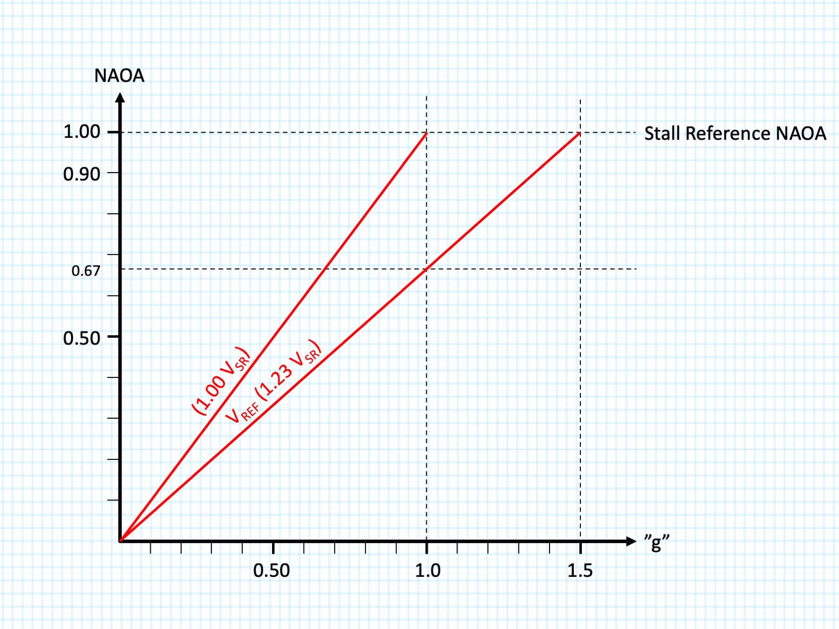
NAOA versus available "g" at VREF
Notice that the intersection of our VREF line and 1.0 g comes to 0.67 NAOA. This would make a good target NAOA on approach for our notional aircraft. If the notional aircraft has an alpha limiter or stick pusher that activates at 0.90 NAOA, we can draw an envelope to indicate an area of operation where the airplane is maneuverable without stalling. Of course, we don’t want to operate below VREF, but this area is available to us in the event of wind shear or other non-normal condition. This becomes useful to us, realizing that if we see an NAOA greater than 0.67 on final approach, because of turbulence for example, we are “eating into” our stall margin.
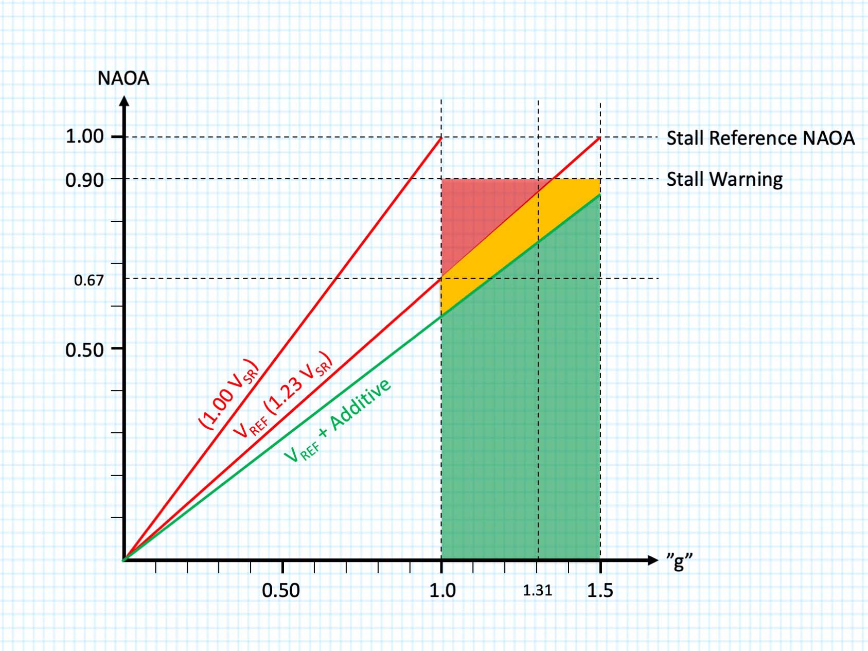
NAOA versus available "g" at VREF, stall margin
Many manufacturers add 5-knots to VREF, or even higher if wind conditions dictate. This results in a lower line on the NAOA-g graph and expands our stall and maneuver margins. Imagine yourself flying at 1g at VREF. You are given a margin before stall warning (the red zone above the line) as well as a maneuver margin. That margin was determined by allowing for a 40° turn on a 3-degree glide path, which comes to 1.31g. These margins can be “eaten” by a sudden gust of wind or turbulence. We certainly don’t want to find ourselves flying this slowly low to the ground when a sudden loss of airspeed activates a stick pusher! Fly-by-wire aircraft could find themselves nearing an “alpha limit,” limiting pitch authority. In either case, it would be wise to avoid high angles of attack.
The impact of sudden gusts on NAOA, g loading, and stall margins
NAOA versus available "g" at VREF, stall margin
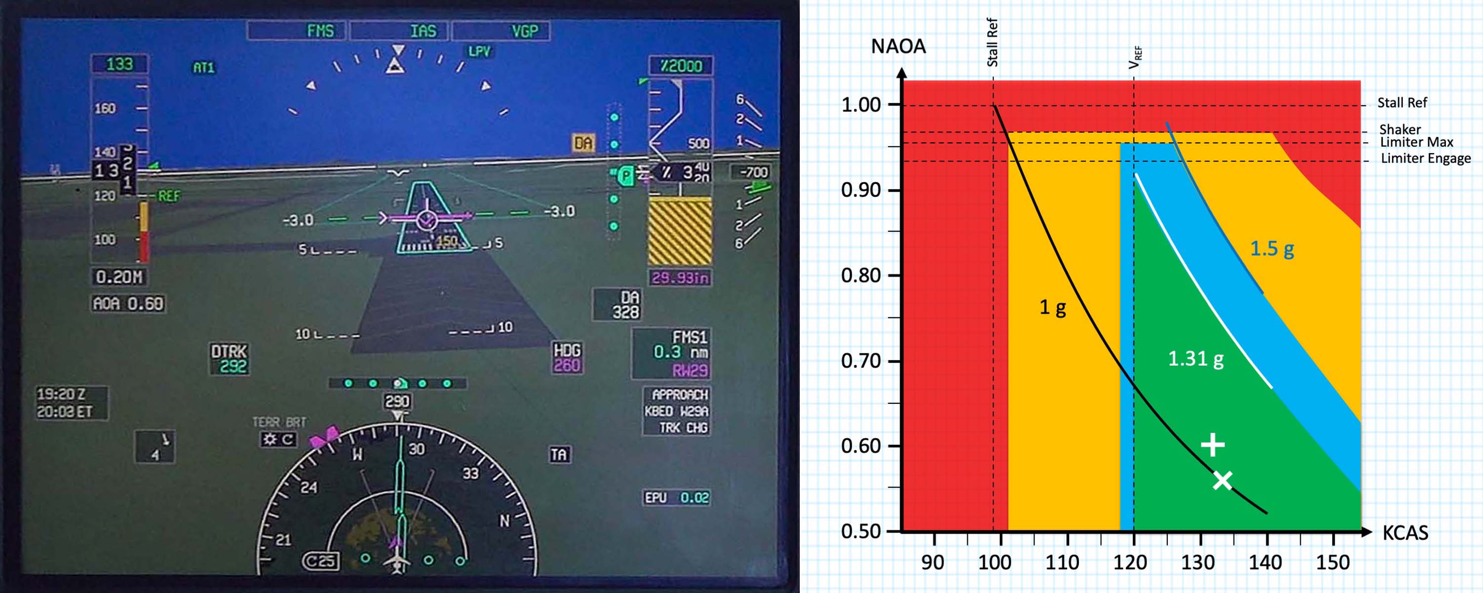
Most pilots are focused on airspeed primarily even if presented with an indication of NAOA. The NAOA-KCAS chart shown for our aircraft is from a recent flight where VREF was 120 knots (at an AOA of 0.67), the winds were at 10 knots, gusting to 18, making our target approach speed 120 plus half of 10, plus 8, for a result of 120 + 5 + 8 = 133 knots (at an AOA of 0.57). Of course, nothing is ever static on a gusty day and just as we expect the airspeed to bounce around, so too does the NAOA. We can see from the photo of the pilot’s synthetic vision, a gust has increased the NAOA to 0.60 and that on the chart our target approach airspeed (shown by the “X”) moves up and to the left (shown by the cross). Our green zone is defined by VREF on the left and the g loading that equates to a 40° bank turn in level flight (1.31 g) to the right. The manufacturer of our notional aircraft has provided us a margin, shown in blue, before we enter a zone of “low speed awareness” which provides an additional margin before stall warning, even at 40° of bank, shown in red. Passing the threshold and entering the flare, it will be okay to go below VREF (in calm conditions) since we no longer need all of the maneuver margin for the design parameter of 40° of bank.
So it should be apparent that getting below VREF is not a good idea and that when it gets windy, you need to add to your approach speed to avoid doing that. But by how much?
Another reason you don't want to get below VREF
You may have heard of the hazards of operating "behind the power curve," but what does that actually mean? The question is more than academic because some aircraft have a VREF that can be said to be in what is more properly called the “backside of the thrust curve.”
The concept of thrust, power, and even horsepower can get messy and perhaps a bit of a history lesson can start to clean things up. Scottish inventor James Watt needed a way of comparing the power of his steam engine to something his customers could relate to, and the unit of horsepower was born. He computed the pulling force of a horse attached to a mill wheel to determine what 1 Horsepower is. Piston engines use a concept called “brake horsepower” from a standard used to measure engine performance by wrapping a cord or belt (the brake) around a shaft. Thrust, on the other hand, is simply the force or “push” in reaction to an engine.
You can plot the parasite and induced drag of a jet airplane against airspeed and equate that to the thrust required to maintain steady, unaccelerated flight. (These curves are different for piston-driven propeller aircraft; we will limit our discussion to jet aircraft.) The point of minimum drag is known as L/DMAX, or "L over D, max." It is simply the point where the ratio of lift over drag is at its maximum.
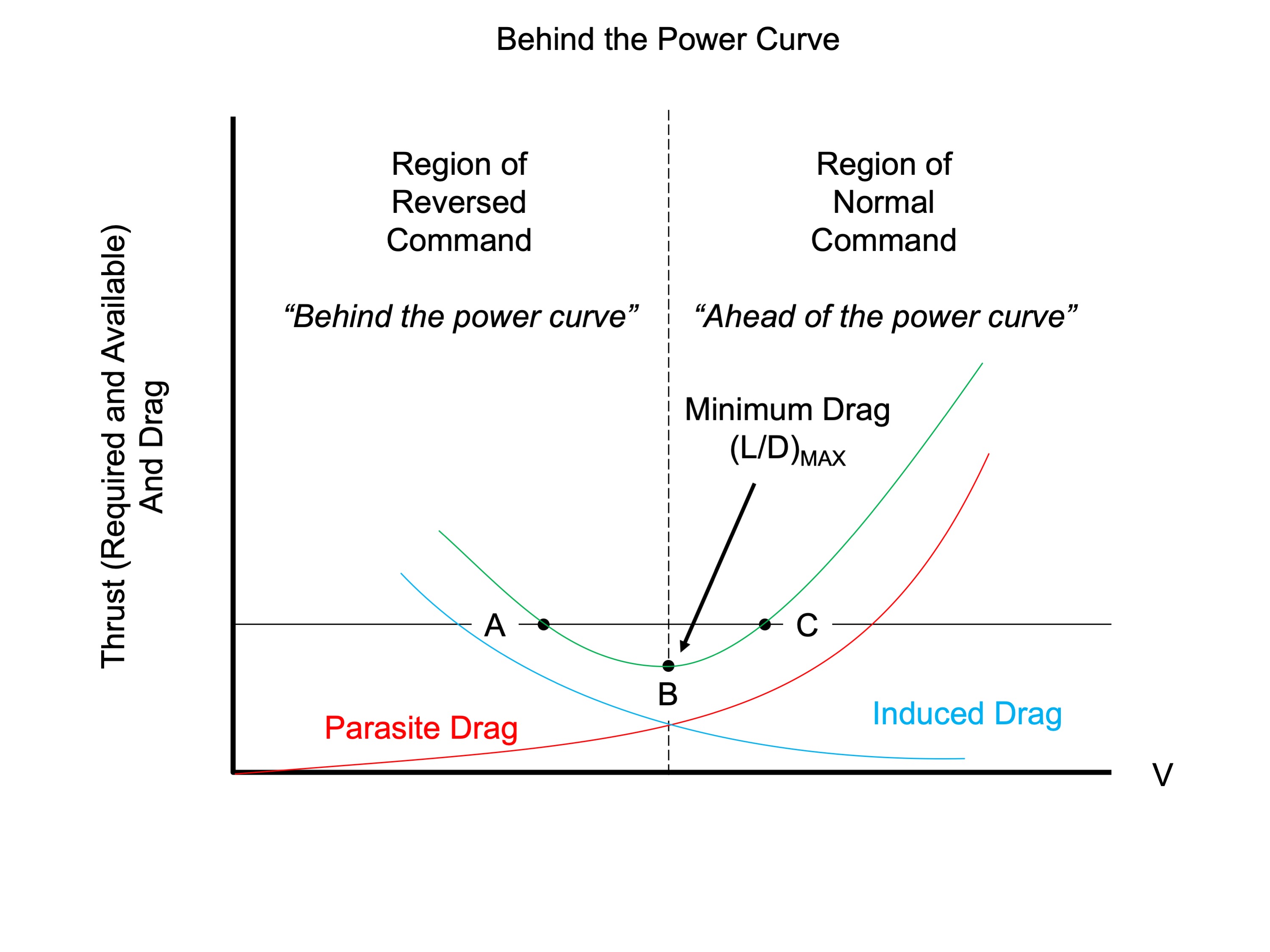
The "power curve"
We transport category aviators spend almost all of our lives "ahead of the thrust curve" where it takes more thrust to fly faster. In the chart shown, for example, Point B is L/DMAX. If you are at Point C and wish to fly at some higher speed, you will need to add thrust, accelerate, and then reduce thrust to a point higher than your original thrust. This seems normal and hence is called the "region of normal command." The airplane tends to maintain a selected speed here. If a gust of wind accelerates you, you don't have sufficient thrust to maintain the higher speed and you tend to fall back to your original, desired speed. The same holds true for something that decelerates you. You will have excess thrust and the airplane will accelerate back to your original, desired speed.
When operating slower than L/DMAX we are operating in the region of reversed command. If you are at Point A in the chart, for example, and wish to pull it back a few knots, you reduce your thrust as before. But now, once you've achieved the lower speed, you will need more than your original thrust setting to maintain the lower speed. The aircraft does not hold speed as easily. If a gust of wind slows you down five knots, for example, your new speed will require more thrust than what you have so you will tend to slow down even further unless you take positive action by adding thrust.
Aircraft with approach speeds on the backside of the thrust curve will not have a tendency to return to targeted airspeeds without active addition of thrust. If a gust of wind slows the airplane down at a constant thrust setting, the speed will continue to decrease until the pilot takes positive action to reverse it. Aircraft with approach speeds on the front side of the thrust curve will be more forgiving, but still bear watching.
3
What wind? What gust?
Not everyone agrees. . .
Some aircraft manuals say you should add half the steady wind and the full gust increment to your approach speed. But that is far from universal. Looking at several aircraft from the smallest Challengers and Falcons to the largest Airbus and Boeing aircraft reveals the breadth of the variation. You might add a half, a third, or none of the steady wind, or the headwind. Most will have you add all of the gust. Most will limit you to a 20-knot total additive, but some lower this to 15 and even 10 knots.

MROC, 21 Feb 2012, Bernal Saborio
Half the wind, all of the gust, up to 20 knots.
If gusty wind conditions are present, add ½ of the steady state wind plus the full gust value to a maximum additive of 20 knots (VREF + 20). VREF will still be the target speed at the threshold.
Source: G450 Airplane Flight Manual, §5.11
But Gulfstream isn't consistent in this. For most of their aircraft this is a recommended procedure. For at least one, the GVII-G500, it is required.
Some Bombardier aircraft have a similar statement.
An other method is used by Boeing, in the 737NG, for example:
Half the headwind, all of the gust, up to 20 knots, but only if the autothrottle is disconnected
If the autothrottle is disconnected, or is planned to be disconnected prior to landing, the recommended method for approach speed correction is to add one half of the reported steady headwind component plus the full gust increment above the steady wind to the reference speed. The minimum command speed setting is VREF + 5 knots.
Source: Boeing 737 NG FCTM, p. 1.11
Dassault has a similar method and they have an even better explanation:
Approach speed (VAPP) is the result of: VREF + wind correction. For wind correction (maximum 20 kt): apply half headwind + full gust increment. COMMENTS: The gust value should be taken into account whatever the wind direction is. For example for RWY 18, wind 120/20G30 given by the ATC: the steady state headwind component is 10 kt (crosswind component is 17 kt) and the full gust is 10 kt so the wind correction should be 15 kt (which is less than 20 kt).
Source: F900EX CODDE2
One-third the headwind, up to 15 knots, gust additive at pilot's discretion
VAPP displayed on the PERF APPR page is equivalent to VLS for gross weight and landing flap configuration, plus an increment based on tower wind component. This increment is equivalent to the higher of 5 kt or 1/3 of the tower headwind component for the landing runway in the F-PLN. [ . . . ] A higher VAPP may be inserted if gust wind or downburst conditions are anticipated but the increment to VLS is limited to 15 kt.
Source: A330/340 FCTM, §6.30.2
Half the crosswind plus all of the gust, up to 20 knots.
Wind correction is half steady state crosswind plus all gust (regardless of direction). Maximum correction is + 20 KIAS.
Source: CL650 OM, Vol 1, §04-08-4
Why the variations?
The reasons for variation may seem arbitrary but might be more strongly correlated to aircraft design and recommended landing technique than one might suspect. All aircraft should be concerned with at least the headwind component because of the nature of winds low to the ground. The wind normally decreases as you near the runway, particularly below 50 feet. Adding at least 5 knots or half the headwind is a way to mitigate that decrease. An airplane that lands in a crab may only be interested in the headwind, since sideslip is not a factor. An airplane that lands in a sideslip (the so-called “wing low” method) or a decrab will have to consider all of the wind, regardless of direction.
The reason for including a wind additive to your approach speed is clearly designed to prevent landing with too little stall margin should the winds change. But landing with too much speed presents its own set of problems.
If you land with that extra speed, will you still be able to stop on the runway available? Many manufacturers recommend you lose any additive prior to crossing the runway threshold. (More on that later.) But that will require considerable judgment.
Will this extra speed throw you into a higher approach category? Some aircraft circle at their final approach speed and an extra 20 knots could very well result in the next higher approach category. This could require a higher circling altitude as well as higher weather minimums.
Will the extra airspeed create problems with tire groundspeed limits? Even if your aircraft manufacturer has not posted tire groundspeed limits, the tire manufacturer most certainly has. These limits can be a factor at higher pressure altitude airports, especially on a day with a low headwind component. On a gusty wind day an additive might bring tire groundspeed limits into play even at lower pressure altitudes.
Will the lower deck angle make it possible to contact the runway nosewheel first? If your airplane flies its final approach in a relatively nose low attitude, touching down too fast could result in a nosewheel first landing with the risk of a nosewheel landing gear collapse. The limits to the approach speed additive should take this deck angle limit into account.
For these reasons, and maybe others, some manufacturers recommend you to get rid of the airspeed additive prior to crossing the runway threshold.
4
Lose or keep the additive?
An opinion . . .
Here again manufacturers differ. Many Boeings, Airbus, and Dassault aircraft leave the additive in until the autothrottles retard for the landing. Some manufacturers recommend the pilot remove the additive prior to crossing the threshold. There are many reasons for caution, but if you decide to lose the additive prior to the runway threshold, how do you do that?
I’ve tried two methods as the pilot flying and I’ve witnessed both methods as the pilot monitoring. Both methods work. Sometimes. But not always. For that reason, I consider both methods to be bad ideas.
Bad Idea One. With or without autothrottles, some pilots will try to get a feel for the gust and try to time pulling the throttles so as to arrive over the threshold at VREF. I found this easier to do in the Gulfstream GV with approach speeds near 110 knots, but even then, I got it wrong now and then. With aircraft requiring higher approach speeds, things are happening too fast for me to time the gust consistently.
Bad Idea Two. With autothrottles, some pilots will manually insert the targeted speed with the additive and select “auto” mode at a moment when they believe the speed is increasing. Here again the judgment. required at higher approach speeds make this a hit or miss proposition.
I consider these bad ideas because a wind gust cannot be predicted consistently. My solution for the last ten years has been to keep the additive until the autothrottles retard for the landing flare, and to ensure I have enough runway in case I touch down with all of the additive speed.
5
Landing distance impact
You have to consider it . . .
When I suggest holding the speed additive to the runway threshold to other pilots, the first reaction is often to ask about landing distance. The landing performance charts in my current aircraft includes a section of up to 20 knots additional speed crossing the threshold. I’ve seen other manufacturers with 10, 15, or 20 knot allowances.
The next objection will be, “what if the gust hits me at just the wrong time and I end up twenty knots fast?” Let’s look at another hypothetical.
Let’s say you have a VREF of 120 knots and a wind straight down the runway at 20 knots gusting to 30 knots. Your charts, like mine, have a section for a headwind up to 40 knots and a speed additive up to 20 knots. You compute your landing distance for a headwind of 20 knots and a gust of 10 knots. Your manufacturer recommends half the steady and all of the gust as an additive, regardless of direction, so your approach speed is 120 + 10 + 10 = 140 knots. That 10-knot gust treats you unkindly and you end up at the threshold at 150 knots airspeed. If your performance data included all of that additional wind you won’t have a problem; your groundspeed will still only be 120 knots.
If your flight management system automatically computes landing distances, you will need to ensure you have the right data in, to get the right data out. It may seem to be common sense to reduce the headwind entry as being conservative, however it paints an inaccurate picture of your actual performance and places a subtle pressure on you to remove the additive.
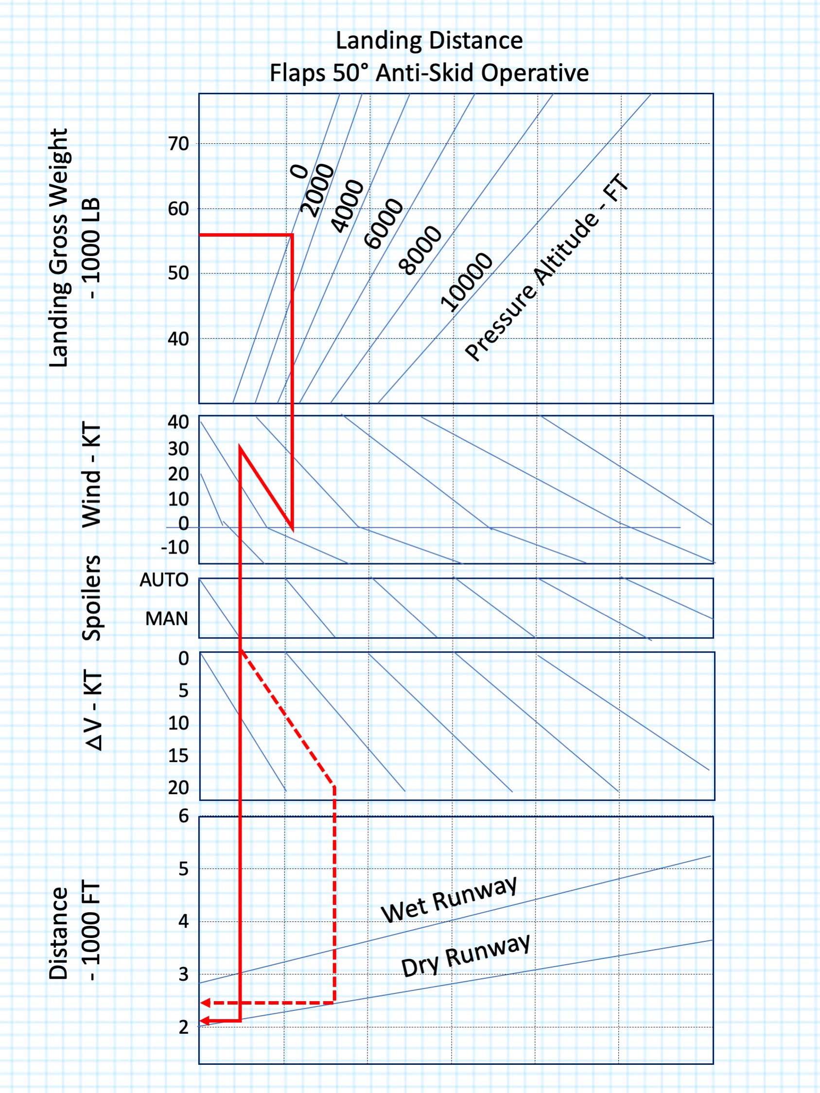
Example landing distance chart
My usual method is to precompute the maximum additive for my normal landing weights at a sea level airport. I use Teterboro Airport (KTEB), New Jersey, because (a) we go there often, and (b) it is usually gusty. In my current aircraft I find that even landing 20 knots fast never increases my landing distance by more than a third on a dry runway and that is good enough for the shortest runway there. If the actual conditions are worse than that, I know I need to dig into the Airplane Flight Manual charts. If I can’t make the numbers work with the additive, my plan is to find someplace else to land. Over the years, I’ve had to do that twice.
In my current aircraft, a Gulfstream GVII-G500, the chore is handled automatically by the avionics, giving me a graphic representation of the resulting landing distance. If I elect to keep my speed additive to the runway threshold, I will know how that will impact my stopping distance.
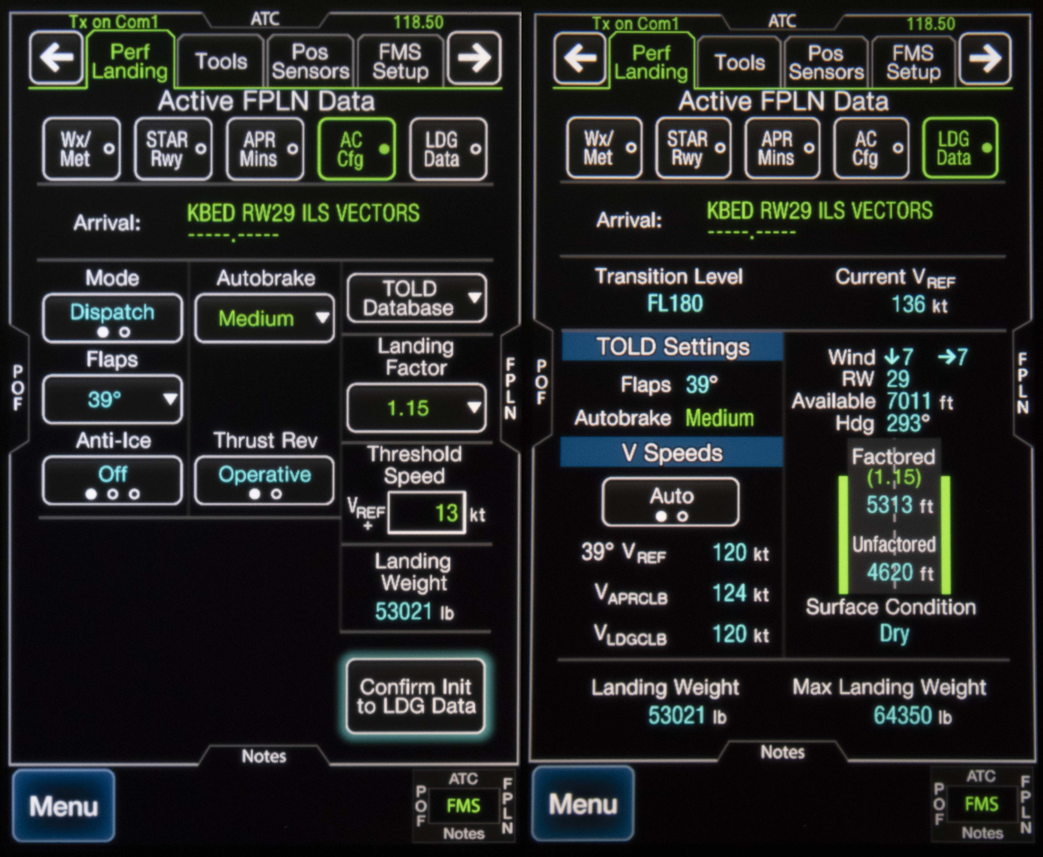
Landing Initialization and Data Pages with 13 knot speed additive, GVII-G500
References
(Source material)
14 CFR 25, Title 14: Aeronautics and Space, Airworthiness Standards: Transport Category Airplanes, Federal Aviation Administration, Department of Transportation
"Approach Speed Control," Boeing Airliner, April 1961, pp. 14-16
Boeing 737 NG Flight Crew Training Manual, Revision 12, June 30, 2013
"Cross-model Wind Additive Reduction Study," Boeing Cross-model Wind Additive Reduction Study, Captain Mark Forkner, March 21, 2018
Dassault Falcon 900EX Crew Operational Documentation for Dassault non EASy (CODDE), Dassault Aviation, March 26, 2010
Gulfstream G450 Airplane Flight Manual, Revision 35, April 18, 2013
Gulfstream GVII-G500 Airplane Flight Manual, Revision 5, March 3, 2020
Please note: Gulfstream Aerospace Corporation has no affiliation or connection whatsoever with this website, and Gulfstream does not review, endorse, or approve any of the content included on the site. As a result, Gulfstream is not responsible or liable for your use of any materials or information obtained from this site.