You could say this hard landing resulting in substantial aircraft damage was caused by the fact the pilots positioned an automatic anti-ice system from AUTO to ALL a little early. You could. But it was really caused by the fact the pilots didn't understand the relationship of the anti-ice system and their fly-by-wire system, and they ran a few checklists from memory, missing the steps that would have prevented all this.
— James Albright

Updated:
2021-04-01
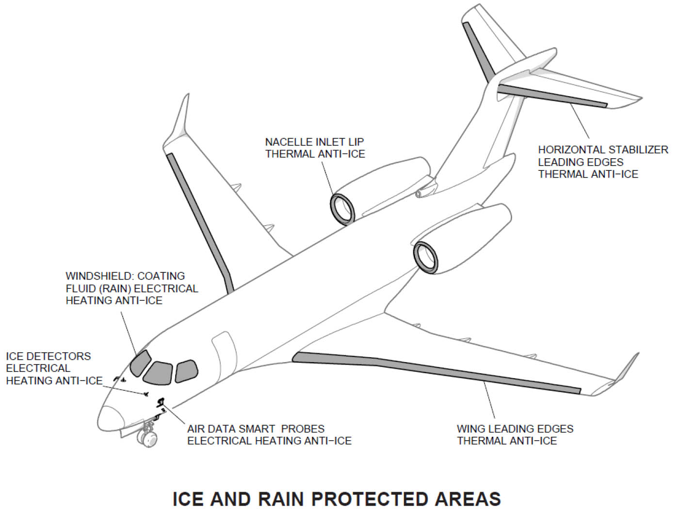
Embraer EMB-550 Ice and Rain Protection Areas,
BEA, Figure 1
We used to say "an airplane is an airplane, they all basically fly alike." How wrong that is. If you are flying a fly-by-wire aircraft, you should understand that you aren't flying the airplane at all. You are managing a series of computers to fly the airplane for you. If you don't understand the rules those computers are using, you can find yourself in a situation where the airplane is doing something you don't understand.
I am as guilty as many pilots are of thinking that I understand something fully, and being tempted to execute corrective procedures without reference to checklists. Let's say you have an automatic anti-ice system that puts on wing and engine cowl anti-ice systems automatically. Now let's say that system isn't working. No big deal, you've operated for years without such a system. In this particular case, the aircraft's flight control computer wants an extra 30 knots of speed before deciding it has had enough and takes control from you. Following the checklist would have told you that.
We often think that any problems on short final are best handled on the ground, so land the airplane. But as the case of Gulfstream G550 N535GA demonstrates, we may not fully understand the problem. In that case and this one, a simple "Go Around" commanded by the first officer could have snapped the captain back into the game. In this case, the first officer reminded the captain to stay out of the red band on the airspeed tape. This particular aircraft also had a yellow band. So does mine. Turbulence and gusts will push the yellow band up now and then. The red band on the airspeed tape is bad news in any airplane. In a fly-by-wire system it is even worse because it means the electrons may soon be in control of your jet, and you might not like what they do with that control.
This case study provides lessons we all need to take to heart, especially those of us flying fly-by-wire aircraft.

1
Accident report
- Date: 27 November 2017
- Time: 0655
- Type: Embraer EMB-550 Legacy 500
- Operator: L39 Engineering
- Registration: RA-02788
- Fatalities: 0 of 3 crew, 0 of 0 passengers
- Aircraft Fate: Substantial
- Phase: Landing
- Airport: (Departure) Moskva-Domodedovo Airport (UUDD), Russia
- Airport: (Destination) Paris-Le Bourget Airport (LFPB), France
2
Narrative
- The crew of the Embraer Legacy 500 were carrying out a private flight from Moscow-Domodedovo airport, bound for Paris-Le Bourget airport.
- At Moscow, a thin film of ice covered the aeroplane and the crew had it de-iced. As icing conditions were prevailing at Moscow airport, the crew set the selector of the ice protection control panel to ALL before starting up the engines. During their start-up, the A-I WINGSTAB FAIL message appeared on the EICAS. The crew tried to reinitialize the system by pressing the WINGSTAB pushbutton and then using the ICE PROT MODE selector. The failure message continued to be displayed.
- Around five minutes after take-off, the STALL PROT ANTICIPATE warning message appeared on the EICAS and remained on the screen until the end of the flight. The captain was PF and the first-officer PM for the arrival at Le Bourget airport. The METARs did not indicate icing conditions. The crew performed the ILS 27 approach at a speed of between 120 and 130 kt.
- At an altitude of 2,200 ft, while the aeroplane was on the ILS glide path, the AOA limiter protection activated itself and the autopilot (AP) automatically disengaged. The aeroplane passed under the glide slope and a glide slope warning sounded. The captain then increased thrust and leveled off in order to return to the approach path. The AOA limiter protection deactivated itself and the crew re-engaged the AP.
- At around 1,000 ft QNH, the AOA limiter protection activated itself again and the AP disengaged. The first officer told the captain to keep the speed above the red tape corresponding to the minimum speed authorized by the protection. This protection limits the angle of attack and did not allow the captain to sufficiently increase the aeroplane’s pitch attitude in order to flare, despite making a full nose-up deflection on the sidestick.
- The aeroplane touched down with a rate of descent of around 1,350 ft/min and a load factor of 4 g. The right main landing gear ruptured and the upper rear hinge made a hole in the upper surface of the wing.
Source: BEA2017-0674 pp. 1-2
3
Analysis
The Crew
- The captain, aged 44 years, is a former instructor on the L-39 Albatros. He obtained his type rating on 24 October 2016 and carried out a simulator training flight session on 17 March 2017. At the time of the occurrence, he had logged more than 1,507 flight hours of which 151 on type.
Source: BEA2017-0674 p. 2
It appears the captain did not have a lot of flight experience and only a year in transport category jets. I've flown the L-39 once and remember it as a docile, easy to fly trainer. One huge difference between these nimble trainers and heavier aircraft is inertia. The trainer has surplus thrust to get you out of trouble. The larger aircraft? Less so.
- The first officer, aged 42 years, was a former airline pilot. He obtained his type rating on 28 August 2017. At the time of the occurrence, he had logged 5,000 flight hours of which 26 on type, all flown in the previous three months.
Source: BEA2017-0674 p. 2
The first officer, while newer to this particular aircraft, had much more relevant flying experience.
The Ice Protection System
- The aeroplane is equipped with an ice protection system. The wing and horizontal stabilizer leading edges along with the nacelle inlet lips are heated with air bled from the engines whereas the air data probes (smart probes and TAT probes) are heated electrically.
- The system can function automatically using the signal sent by an ice detector positioned on the nose of the fuselage or manually via the control panel on the cockpit overhead panel.
- The selector on the ice protection control panel can be set to one of the following three positions:
- AUTO: the system automatically activates the heating of the wing and horizontal stabilizer leading edges along with the nacelle inlet lips on receiving the signal sent by the ice detector.
- ENG: forces the heating of the nacelle inlet lips on the ground and in flight, without taking into account the ice detector.
- ALL: forces the heating of the wing and horizontal stabilizer leading edges along with the nacelle inlet lips, without taking into account the ice detector.
Source: BEA2017-0674 pp. 3-4
This setup will look familiar to many Gulfstream pilots, but actually simpler. We never turn on the wing anti-ice without the engine cowl anti-ice system, so this does the same thing with a single switch.
The Ice Protection System
- The ICE SPEED RESET position reinitializes the speeds associated with the AOA limiter protection in icing conditions with the values calculated in non-icing conditions. This action is carried out when the aeroplane has left icing conditions and the crew have checked that there is no ice accretion on the plane. It only functions if the ice protection system is operational.
- As soon as a failure is detected by one of the BITE tests, a message is displayed for the crew on the EICAS.
- An amber A-I WINGSTAB FAIL caution type message is displayed on detection of a failure of the anti-icing system of the wing and horizontal stabilizer leading edges.
- This message also appears when the ICE PROT MODE selector is set to ALL before engine start-up as the leading edge pneumatic heating system cannot be supplied in this situation. This is why the Internal Safety Inspection procedure, to be carried out before engine start-up, requires the ICE PROT MODE selector to be set to AUTO.
Source: BEA2017-0674 pp. 3-4
The Fly-by-wire System
- The Embraer Legacy 500 is equipped with a fly-by-wire control system which controls and monitors the primary control surfaces (ailerons, elevators and rudder) and the secondary control surfaces (trimmable horizontal stabilizer, flaps and spoilers when used as speed brakes or ground spoilers).
- Two operating modes are available: Normal Mode (NM); Direct Mode (DM).
- In NM, crew actions on their sidestick and on the rudder pedals are sent to the two Flight Control Computers (FCC). The FCCs then calculate the position of the control surfaces based on flight controls laws, taking as inputs, the sidestick position along with other data such as the air and inertial data or flap position.
- In DM, the position of the flight control surfaces is directly linked to the crew’s actions on their sidestick and rudder pedals. In this operating mode, the aeroplane behaves like a conventional plane.
- The flight control laws implemented by the flight control system in NM provide functions designed to prevent the aeroplane from leaving its flight envelope.
- One of these functions, the AOA limiter protection, protects the aeroplane, in particular, from a low speed stall by limiting the maximum angle of attack of the plane. This protection is activated when the angle of attack exceeds a certain threshold or when the indicated airspeed passes below the Vaoa speed symbolized by the top of the amber tape represented on the speed tape (see diagram below).
Source: BEA2017-0674 pp. 4-7
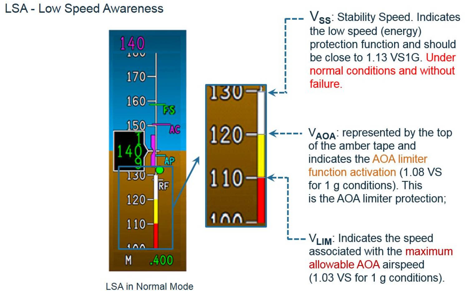
Embraer EMB-550 Speed Tape, BEA, Figure 4
- When the indicated airspeed is in the amber tape area, the AP is automatically disengaged. The nose-up inputs on the sidestick will then control an angle of attack instead of a load factor and the control law will calculate the position of the control surfaces in order to reach the corresponding angle of attack. If the pilot makes a full backstick input with constant engine thrust, the angle of attack increases and the indicated airspeed decreases to the minimum value Vlim corresponding to the maximum angle of attack authorized to keep a sufficient margin against stalling. The control law prevents the maximum angle of attack from being exceeded, irrespective of the sidestick position. If the pilot returns his sidestick to neutral, then the control law positions the control surfaces so that the indicated airspeed increases to Vaoa.
- The activation of the AOA limiter protection is both represented on the PFD speed scale and symbolized on the PFD horizon by means of the PLI. The PLI is displayed on the attitude scale and shows the margin with respect to Vaoa and Vlim. When the margin is sufficiently large, the PLI is not displayed. When there is a reduced margin, the PLI is displayed in either yellow or red: if the speed decreases to below Vaoa, then the PLI is displayed in yellow, if the speed reaches Vlim, the PLI is displayed in red.
Source: BEA2017-0674 pp. 4-7

Embraer EMB-550 PFD when AOA protection active, BEA, Figure 5
- The calculation of the Vaoa and Vlim speeds is carried out by the FCCs and depends on numerous parameters. The presence of icing conditions and the correct operation of the ice protection system are taken into account to calculate these speeds.
- When a failure of the ice protection system is detected and the aeroplane encounters icing conditions during the flight (determined from the system’s view point by the activation of the ice detector or by the manual setting of the control panel selector to ENG or ALL), the angle of attack values to activate the protection and the maximum angle of attack values are significantly reduced. The Vaoa and Vlim speed values are increased. In this situation, in addition to the message associated with the failure encountered, the STALL PROT ANTICIPATE information message is displayed on EICAS to inform the crew that the Vaoa and Vlim thresholds have been increased. These conditions remain up to the end of the flight whatever the meteorological conditions and the position of the ICE PROT MODE selector.
Source: BEA2017-0674 pp. 4-7
The Captain's Statement
The captain said that there had been light freezing drizzle during the night. A thin film of ice covered the RA-02788. Before start-up, the aeroplane had been de-iced using a lorry. The captain started up with the first officer. During the start-up, they positioned the selector on the ice protection control panel to ALL. A failure warning was then triggered. They changed the position of the selector to AUTO which made the message disappear. According to him, the message had appeared because the aeroplane had remained at a standstill and they had not started taxiing.
Source: BEA2017-0674 p. 8
What Really Happened, and Should Have Happened
FDR data shows that in reality the A-I WINGSTAB FAIL message was still present.
Source: BEA2017-0674 p. 8
The pilots positioned the anti-ice system to ALL "during" engine start which tells me they probably did this before, but certainly not after. That was against procedure because it forced the system on without available bleed pressure and is the reason they got the WINGSTAB FAIL message.
- The OPERATION IN ICING CONDITIONS normal procedure is described in the flight manual. It indicates, in particular, that the ICE PROT MODE selector must be set to ALL after engine start-up if the outside air temperature is below 5 °C and there is a possibility of climbing through clouds in the climb out up to a height of 1,700 ft.
- The analysis of the FDR data found that the crew had set the ICE PROT MODE selector to ALL before starting up the engines. Setting the selector to this position before start-up generated the display of the A-I WINGSTAB FAIL message.
Source: BEA2017-0674 pp. 10-11
There is a checklist procedure to fix all this and it requires the system be returned to AUTO first. I think the crew simply reset the system by deselecting/reselecting the ICE PROT WINGSTAB button (as the checklist calls for) with the system still in ALL (against checklist procedure).
- The A-I WINGSTAB FAIL abnormal procedure is described in the flight manual. It assumes that the ICE PROT MODE selector is set to AUTO.
- This procedure does not enable the crew to reinitialize the ice protection system in the specific case where the warning appears during engine start-up with the selector set to ALL, and the A-I WINGSTAB FAIL message stays on the EICAS. In this case, the ICE PROT MODE selector must be set to AUTO and the system must be reinitialized by pushing to OFF and then ON the WINGSTAB button on the ice protection control panel.
- The analysis of the flight parameters found that, on the ground at Moscow, the crew had unsuccessfully tried to reinitialize the ice protection system with the ICE PROT MODE selector set to ALL and not to AUTO.
Source: BEA2017-0674 p. 12
The crew elected to takeoff with the error still uncorrected and neglected the next checklist in the sequence.
- According to this procedure, when the A-I WINGSTAB FAIL message persists in icing conditions, the STALL PROT ANTICIPATE procedure must be complied with.
- The STALL PROT ANTICIPATE abnormal procedure says to add 30 kt to the reference speed with full flaps and to apply a factor of 1.7 to the landing distance.
- During the approach to Le Bourget airport, the aeroplane speed was between 120 and 130 kt. The application of the STALL PROT ANTICIPATE procedure requires that an approach speed of 144 kt be adopted for a landing distance of 1,219 m.
Source: BEA2017-0674 pp. 12-13
4
Cause
- The crew undertook the flight to Le Bourget airport despite the presence of the A-I WINGSTAB FAIL message and icing conditions at departure from Moscow. The occurrence of the failure is linked to the activation of the ice protection system in the ALL position before engine start-up. The procedure associated with this failure, as written at the time of the accident, did not enable the crew to reinitialize the ice protection system. The BEFORE TAKEOFF procedure and then the consultation of the MEL should have resulted in the crew postponing the flight.
- During the climb, the appearance of the STALL PROT ANTICIPATE message on the EICAS informed the crew of the increase in AOA limiter protection activation speeds. The associated procedure should have led the crew to increase the reference speed by 30 kt during the approach.
Source: BEA2017-0674 p. 15
References
(Source material)
Investigation Report, Accident to the Embraer EMB-550 Legacy 500 registered RA-02788 on 27 November 2017, Bureau d'Enquètes ed d' Analyses pour la sécurité de l'aviaiton civile (BEA), BEA2017-0674