Imagine yourself flying a B-17 when a German ME-109 runs into you, nearly slicing off your tail. Will the airplane keep together as you configure and slow for landing? (On 1 February 1943 it did.) Now what does this have to do with flying today?
— James Albright

Updated:
2017-12-01

Boeing B-17F-5-BO 41-24406,
1 February 1943 (USAF photo)
Imagine yourself flying a business or commercial jet when an Airbus A380 crosses your path just 1,000 feet above you and it takes every bit of airmanship and physical strength in you to return the airplane to straight and level flight. You suspect the aircraft may be bent. Well you don't have to imagine that, it happened to the crew of Challenger 604 D-AMSC on January 8, 2017.
Or, what if your autopilot tells you, while happily crossing the pond, that the aileron is having problems keeping the wings level and when you disengage the autopilot the airplane snaps into a roll? (This happened to Challenger 604 C-GKTO on November 18, 2017 while flying from Europe to Canada. They suspect a water leak forward of aileron trim cables from those cables.)
Or, what about a lightning strike? Aircraft icing? Assymetric flaps? Hail damage? Bird strike? Debris from another aircraft on the runway?
Or, . . . you get the idea. Now you have doubts about how airworthy your aircraft actually is.
You may need to borrow a page from military aviation: the controllability check.
There isn't a lot written on the subject. When I was in Air Force pilot training, it was a subject from day one because the aircraft were not as reliable as they could have been and we did a lot of formation flying where the chance of a midair collision was always considered. So we talked about how to do controllability checks and every now and then we did them. My only experience with doing controllability checks was while doing Functional Check Flights, and that is a good place to consider the how. But let's first consider the why.
On 1 February 1943, the 414th Bombardment Squadron (Heavy) was on a mission to attack the port of Tunis. A single-engine Messerschmidt 109G fighter collided with "All American III," a Boeing B-17F-5-BO Flying Fortress, 41-24406. The fighter cut diagonally through the bomber’s fuselage, carried away the left horizontal stabilizer and elevator, and damaged the flight control cables. The B-17 made it to its home base (Biskra, Algeria) after flying for another 90 minutes. None of the ten crewmembers were injured.
The aircraft was repaired and returned to service. It flew until the end of the war, at which point it was dismantled for salvage.
2 — Case study: Alaska Airlines 261
4 — Why do a controllability check?
5 — How to do a controllability check
6 — C-17A controllability check

1
Case study: Elal 1862
The odds were stacked against this crew, no doubt about it. They didn't have all the information they needed and may have felt a sense of urgency to get the airplane on the ground. But the airplane was flyable. A controllability check would have helped them understand the new flight characteristics of their two-engine Boeing 747 while providing the time needed to reduce their gross weight.
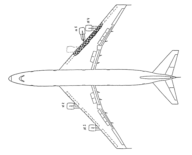
El Al 1862 estimated damage to RH wing leading edge, from Nederlands AAR 92-11, figure 4.
This cargo Boeing 747 took off performance limited (they were as heavy as they could have been under the conditions) and had the number three engine take out the number four engine. That cost them some of their flight controls and they definitely had their hands full. And yet they were able to fly for eight minutes, maintaining altitude and heading when they wanted. They began fuel dumping almost immediately. But as they slowed the increasing angle of attack overwhelmed the thrust available and they ended up behind the power curve and outside their roll capability. The Nederlands accident report says, "Because of the marginal controllability a safe landing became highly improbable, if not virtually impossible."
That might be true. But there are a few things we can take away from this:
- If the airplane is flying but continued flight is questionable, try to reduce gross weight before reducing airspeed or increasing drag.
- If faced with a loss of thrust on one side, attempt to make turns into the good engine(s) to improve roll out capability.
- If you don't have to land immediately and controllability is in question, look for a remote area where you can do a controllability check. (Attempt to slow the aircraft to approach speed and configure for landing at altitude; doing so with enough altitude to recover if things go wrong.) This gives you a better idea of how fully you can configure and how slowly you can fly.
For more about this accident, see: El Al 1862.
2
Case study: Alaska Airlines 261
The pilots of Alaska Airlines 261 were given an airplane set up to fail and were heroic in their efforts to save it once it did fail. The stabilizer trim system failed and would have made for a challenging landing. The crew, in consultation with experts on the ground, tried several methods to free the stabilizer which ultimately caused it to break free of its structural mounts, making the airplane truly unflyable. The crew did nothing wrong; it was the mindset of the time to fix what is broken, not to accept the degraded flying condition of the aircraft. But had they ceased their troubleshooting and attempted a controllability check, they may have realized the airplane could have been safely landed.
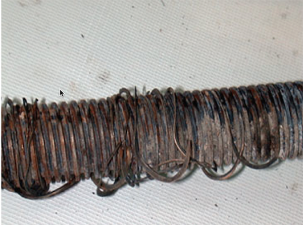
The recovered acme screw, from NTSB Report, Figure 12c.
First a few facts: The MD-80 was designed without a fail safe mechanism on the horizontal stabilizer. Alaska Airlines extended lubrication, inspection, and replacement intervals on the horizontal stabilizer on this particular aircraft. A lead mechanic at Alaska Airlines' Oakland maintenance facility reported maintenance short comings to the FAA fifteen months prior to the crash, and was placed on paid leave. As it turns out, over two years prior, he had ordered the horizontal stabilizer jack screw on this aircraft be replaced. His recommendation was overruled by the next shift. The aircraft was put back into service, its next overhaul would be in two and a half years.
On 31 January 2000, the pilots flying this airplane at first experienced a jammed stabilizer. They accomplished the appropriate checklists and ended up with an airplane that was barely controllable. The horizontal stabilizer jack screw was bare of any lubrication and the threads had been ground off. The stabilizer would not budge. There were no procedures on what to do next and the pilots thought a successful landing was in doubt. They elected to use primary and secondary motors to free the stabilizer. This moved the stabilizer free and dislodged a retaining nut on the stabilizer. The stabilizer moved violently enough to completely dislocate the jack screw. The airplane entered an uncontrollable dive and all were killed.
Given all that, the pilots did what they could and in accordance with their training. But what if, after they had gone through all of the trouble shooting procedures had they decided to attempt to land the aircraft with the stabilizer frozen? A controllability check could have given them the confidence to attempt the landing and not risk repeatedly activating the trim motors in an attempt to free the stabilizer.
For more about this accident, see: Alaska Airlines 261.
3
Case study: Qantas 72
Not all flight control problems are mechanical, especially if you are flying an Airbus. Captain Kevin Sullivan was flying an Airbus A330 that came out of the factory with a computer design flaw that would only occur in a very rare set of circumstances, but those circumstances meant he no longer had any control of the aircraft until the computers decided they had messed things up. He brought the airplane in for a safe emergency landing after flying a controllability check. Knowing the aircraft could be configured from a safe altitude gave him the confidence to attempt the landing off a controlled, 3-degree glide path, fully configured.
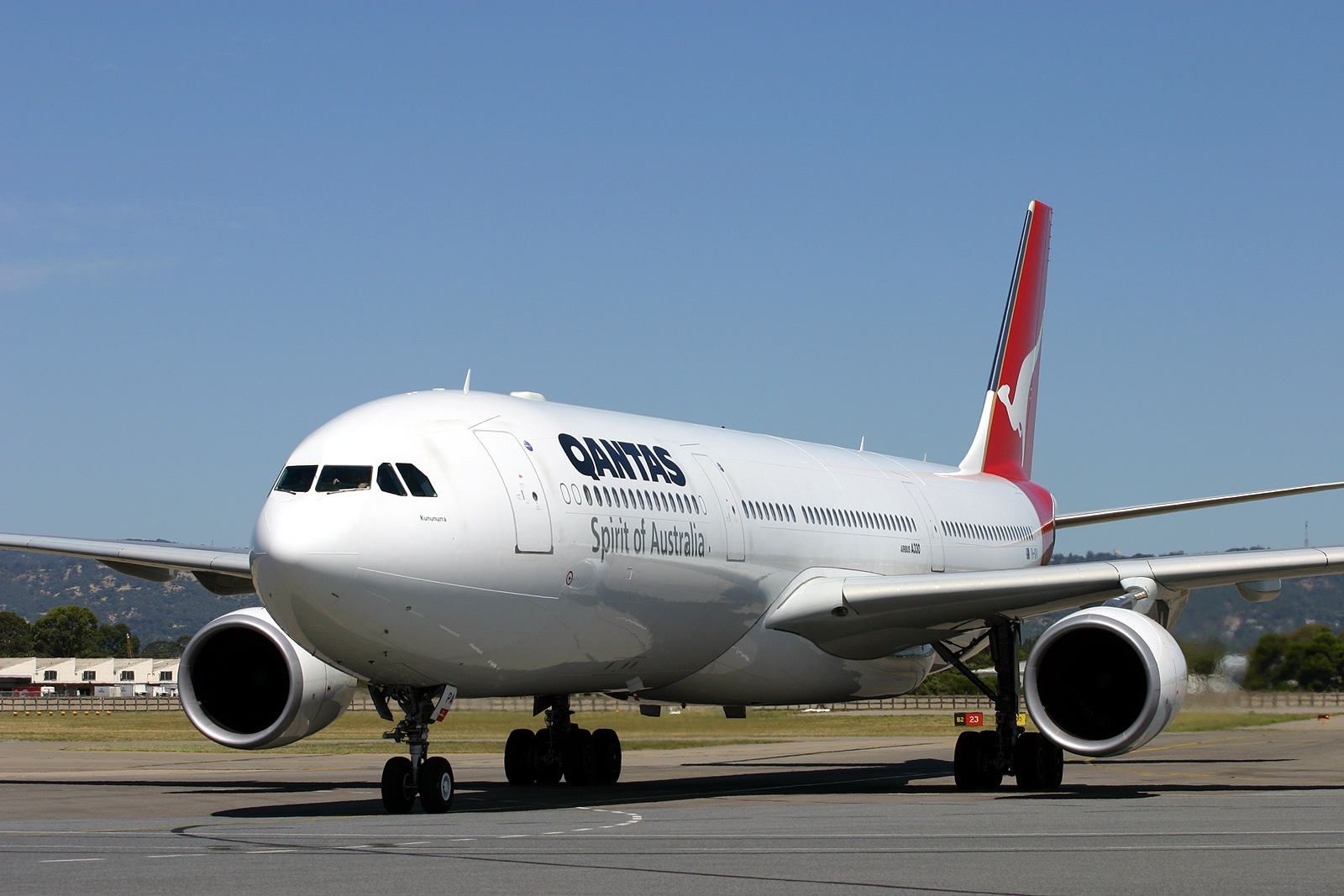
Airbus A330-303 VH-QPA, Adelaide, Australia (Chris Finney)
The Airbus A330 was designed to give priority to the computers over the pilots when it comes to deciding what to do with the flight controls, with the aim of preventing pilot error. It works pretty well, except for when it doesn't. In the case of Qantas Flight 72 on October 7, 2008, the errant computers nearly dropped a perfectly flyable airplane into the Indian Ocean. A level headed captain with experience as a U.S. Naval aviator saved the day. Among the many tools in his arsenal was a controllability check.
I asked Captain Sullivan about the controllability check and he was unequivocal about its importance that day. "For the QF72 accident, our electronic flight controls were operating at an unknown level and I had serious concerns as to their veracity and my level of control, especially close to the ground. Two uncommanded pitch downs with no amplifying information from ECAM meant we were in unchartered territory, so the control check confirmed flap operation and appropriate control stick response, at altitude, prior to landing."
For more about this, see: Qantas 72.
4
Why do a controllability check?
It seems to me that there is almost never anything to lose by doing a controllability check unless you are on fire, running out of fuel, or perhaps the weather coming down or there is some other time constraint. There are times where doing a controllability check can be a life saver.
You should probably consider doing a controllability check if:
- An element of your flight control system has been damaged or appears to be restricted.
- The aircraft's aerodynamics appear to be compromised.
- The aircraft's lateral or vertical balance appears to be shifted outside of design limits.
- The aircraft has sustained damage due to hail, icing, or other weather affects.
There are times when doing the controllability check is vastly preferable to "ad hoc" troubleshooting.
Troubleshooting beyond checklist directed actions is rarely helpful and has caused further loss of system function or failure. In some cases, accidents and incidents have resulted. The crew should consider additional actions beyond the checklist only when completion of the published checklist steps clearly results in an unacceptable situation. In the case of airplane controllability problems when a safe landing is considered unlikely, airplane handling evaluations with gear, flaps or speedbrakes extended may be appropriate. In the case of jammed flight controls, do not attempt troubleshooting beyond the actions directed in the NNC [Non-Normal Checklist] unless the airplane cannot be safely landed with the existing condition. Always comply with NNC actions to the extent possible.
Source: B737 NG Flight Crew Training Manual, §8.2
5
How to do a controllability check
There isn't a lot written about how to do a controllability check, but we can take clues from our objectives and a few other sources.
The objectives of a controllability check
What are we trying to accomplish? We are trying to get the airplane back on the ground in one piece and in order to do that we need to:
- Get the airplane configured: will the landing gear come down in a landable condition?
- Get the airplane configured: will the flaps extend fully, and if not, how far will they extend?
- Get the airplane slowed: will you be able to fly normal approach and landing speeds?
(Some aircraft land better gear up than with some combinations of main and nose gear. Finding out early may give you a chance to try alternate methods of gear retraction or, if that fails, retracting the gear to a more favorable combination.)
(If the flaps move, will they move symmetrically? Finding out early may steer you to another runway or affect the way you fly the approach.)
(If the aircraft starts to misbehave while decelerating to normal approach speeds, you may want to limit your speeds when making your actual approach to landing.)
Manufacturer Recommendations
Boeing
- Unless circumstances such as imminent airplane breakup or loss of control dictate otherwise, the crew should take time to assess the effects of the damage and/or conditions before attempting to land. Make configuration and airspeed changes slowly until a damage assessment and airplane handling evaluation have been done and it is certain that lower airspeeds can be safely used. In addition, limit bank angle to 15° and avoid large or rapid changes in engine thrust and airspeed that might adversely affect controllability. If possible, conduct the damage assessment and handling evaluation at an altitude that provides a safe margin for recovery should flight path control be inadvertently compromised. It is necessary for the flight crew to use good judgment in consideration of the existing conditions and circumstances to determine an appropriate altitude for this evaluation.
- The evaluation should start with an examination of flight deck indications to assess damage. Consideration should be given to the potential cumulative effect of the damage. A thorough understanding of airplane systems operation can greatly facilitate this task.
- If structural damage is suspected, attempt to assess the magnitude of the damage by direct visual observation from the flight deck and/or passenger cabin. While only a small portion of the airplane is visible to the flight crew from the flight deck, any visual observation data can be used to gain maximum knowledge of airplane configuration and status and can be valuable in determining subsequent actions.
- The flight crew should consider contacting the company to inform them of the situation and use them as a potential source of information. In addition to current and forecast weather, and airfield conditions, it may be possible to obtain technical information and recommendations from expert sources. These expert sources are available from within the company as well as from Boeing.
- If controllability is in question, consider performing a check of the airplane handling characteristics. The purpose of this check is to determine minimum safe speeds and the appropriate configuration for landing. If flap damage has occurred, prior to accomplishing this check, consider the possible effects on airplane control should an asymmetrical condition occur if flap position is changed. Accomplish this check by slowly and methodically reducing speed and lowering the flaps.
- Lower the landing gear only if available thrust allows. As a starting point, use the flap/speed schedule as directed in the appropriate NNC [Non-Normal Checklist]. If stick shaker or initial stall buffet are encountered at or before reaching the associated flap speed, or if a rapid increase in wheel deflection and full rudder deflection are necessary to maintain wings level, increase speed to a safe level and consider this speed to be the minimum approach speed for the established configuration.
- After the damage assessment and handling characteristics are evaluated, the crew should formulate a sequential plan for the completion of the flight. If airplane performance is a concern, use of the alternate flap or gear extension systems may dictate that the check of airplane handling characteristics be done during the actual approach. Configuration changes made by the alternate systems may not be reversible. The crew must exercise extreme caution on final approach with special emphasis on minimum safe speeds and proper airplane configuration. If asymmetrical thrust is being used for roll control or pitch authority is limited, plan to leave thrust on until touchdown.
Source: B737 NG Flight Crew Training Manual, p. 8.36
6
C-17A controllability check
What used to be "tribal knowledge" eventually became procedure in the Big Airplane Air Force and perhaps the best example of that is with the C-17 controllability check procedure.
A controllability check is conducted to determine the effect of structural damage, in-flight control malfunctions, airspeed differences, or fuel imbalance, on control of the aircraft. Conduct the check at 5,000 to 10,000 feet AGL, if possible.
- Monitor control stick and rudder pedal position, as well as control surface movement indicated on the MFD [Multifunction Display] CFG [Configuration] format, to determine control authority remaining.
- The pilot must use prudent judgment in making speed and configuration changes.
- As airspeed and configuration are varied, be alert for aircraft buffet. Do not decrease speed below the minimum configuration maneuvering speed.
- Factors such as turbulence and crosswind, must be considered when determining a configuration and speed with adequate control margin best suited to approach and landing. Apply estimated crosswind controls required for landing to test effect on flight characteristics.
- Once the limiting configuration and minimum safe speed have been determined, fly that speed plus 10 knots during approach and landing. Refer to Abnormal Configuration Procedures, as appropriate.
WARNING: If control authority degrades rapidly or required control input approaches the limits of authority about any axis, with configuration change and/or airspeed variation, immediately return to a configuration and speed at which adequate control authority is known to exist.
WARNING: The speed must never be decreased to the point at which full control deflection is required about any axis since there may be no recovery capability beyond this point. This can occur with no unusual stick or rudder positions since EFCS is applying controls with no feedback to the pilots.
Source: T.O. 1C-17A-1, ¶3-440
This has always been my favorite warning in any Air Force manual over the years. I once — and only once — found myself at full control deflection in flight and this warning was the first thing that popped into my head when that happened. I think it may have saved me that day.
- The approach speed must never be allowed to decrease below the minimum safe maneuvering speed as determined from this check. Routinely, fly minimum safe speed plus 10 knots as the target approach speed.
Source: T.O. 1C-17A-1, ¶3-440
7
Functional Check Flight (FCF) example
Looking at a Functional Check Flight manual can show the care and diligence needed during a controllability check. Most business jet manufacturers are reluctant to release these manuals to their customers. The USAF insisted and the C-37 (GV/550) manual offers a few good pointers.
Note that things are done slowly, methodically, and with limits in mind. The biggest mistake I saw with new and inexperienced functional check pilots was the desire to rush things, especially when validating low speed flying characteristics. The Air Force manuals during my time doing these things were written to require decelerations no faster than 2 knots per second. This updated manual lowers that to 1 knot per second. I like that better. The critical point for these maneuvers is you are not trying to duplicate a simulator stall event or demonstrate exceptional pilot skills. Your aim is to demonstrate the airplane can fly at the charted stall warning speed. In the context of a controllability check, you only want to demonstrate that the airplane can be controlled for landing. There is no point going any slower than the speed you expect for that landing.
Please note I offer the following not as a narrative on how to do a controllability check, but to demonstrate the deliberate nature of a functional check flight. Everything is done methodically with the eye that if something doesn't go right, the subsequent steps may have to be aborted.
Climb to 15,000 Feet
- Flight Control Freeplay, Friction & Breakout . . . CHECK
- Select FLIGHT CONTROL Synoptic Page.
- Pilot and copilot should each in turn maneuver the aircraft by hand.
- One axis at a time, evaluate aileron, elevator, and rudder controls. Beginning in neutral, there should be no perceptible looseness or deadband to an extent which would make small, precise inputs difficult. The initial control pressure (breakout force) to produce an aircraft response should not be so high as to make small inputs difficult, nor should it abruptly decrease and cause overshoots. Resistance felt during control movements should be relatively constant with no rough spots, bumps or binding.
- Altimeter/ASI Check (Zero Sideslip, 250 KCAS) . . . RECORD
- At 250 KCAS in straight flight with no sideslip, record pilot (MADC 1), copilot (MADC 2) and standby indications.
- Pilot and copilot PFD indications should in each case agree within 2 knots and 40 feet. Standby airspeed and altitude should match MADC 2 within ±5 knots and ±150 feet.
- Spoiler Control (Speedbrake Blowdown) . . . ON / CHECK
Source: USAF C-37 Functional Check Flight Manual, pp. 34-37
For the purposes of a controllability check, if you have damage to the wings or suspect you may have problems with the spoiler system, you should consider whether you need the spoilers for the landing. If not, you might be better off not testing them and leaving them stowed.
- Select A/P and A/T to OFF
- Deploy Speedbrakes Fully at 250 KCAS
- Select Spoiler Control to OFF
- The spoilers should blow down symmetrically.
- Slow to 170 KCAS with 20° Flaps / Gear Down
- The spoilers will float with increasing flap extension.
- There should be no lateral trim change due to asymmetric floating.
- Retract Speed Brakes
- Retract Gear & Flaps
- Select Spoiler Control to ON
- Verify Spoilers Stow
Source: USAF C-37 Functional Check Flight Manual, pp. 34-37
Descend to 10,000 Feet
- Landing Gear & Flap Operation . . . CHECK
Source: USAF C-37 Functional Check Flight Manual, pp. 34-37
Depending on why the controllability check is needed, you might consider leaving the gear down once it is extended. If you suspect damage to the wing, you may also want to consider limiting flap extension to only as needed for the landing.
- This test is arranged to provide a very efficient procedure for checking landing gear and flap operation at their limiting speeds, along with the associated Aircraft Configuration warnings for 39° flaps without gear down, and for speedbrakes extended with gear or 39° flaps.
- It is most easily performed in an autopilot vertical speed descent of 500 to 1000 fpm using manual power adjustments to control speed.
- Follow the sequence outlined on the test card exactly.
- Extend & Retract Speedbrakes – Aircraft Configuration and Speed Brake Extended messages illuminate
- Low-Altitude Stall Warning / Stall Barrier Checks . . . PERFORM & RECORD
250 KCAS – Flaps 10°
225 KCAS – Landing Gear DOWN
225 KCAS – Landing Gear UP
220 KCAS – Flaps 20°
170 KCAS – Flaps 39°
Landing Gear Warning – No Silence
Extend & Retract Speedbrakes – Aircraft Configuration and Speed Brake Extended messages illuminate
170 KCAS – Flaps 39°
220 KCAS – Flaps 10°
250 KCAS – Flaps UP
10,000 Foot Checks
Source: USAF C-37 Functional Check Flight Manual, pp. 34-37
I offer the following only to show the pacing of the functional check flight process, especially the rate at which speed is reduced. For the FCF, the aircraft is taken to the point at which stall warning is activated. You should not do this for a controllability check. I would go no slower than approach speed and would even consider adding 10 knots to that if landing distance permits.
- Verify aircraft gross weight, look up shaker and pusher speeds and enter in the spaces provided.
- Verify system operation by first performing a clean configuration push to confirm both shakers and stall barrier valves operate properly.
- Cross check AOA indications while slowing and be alert for sticking probes or airspeed splits.
- The stick shaker should actuate at .85 AOA ±0.01 and the pusher at 1.00. ±0.01. Accuracy of data is dependent on entry rate. At the desired rate of one knot per second, pusher should occur within ±3 knots of schedule. Shaker onset speed can vary as much as ±3 KCAS. This test is to confirm there is a distinctive warning prior to pusher. When the push occurs, the amber STALL BARRIER 1-2 message will illuminate on CAS, then extinguish after the control column is pushed forward.
- Perform the remaining tests as outlined on the flight card. Record the gross weight prior to each test.
- Record the gross weight prior to each test.
- With both systems operating, record airspeed and AOA at shaker and pusher activation. Airspeed tolerance for pusher is ±3 KCAS. Do not slow more than 5 KCAS below charted pusher speed if the stall barrier has not activated.
- If required due to weather or turbulence, test altitude may be adjusted higher (max 2000 feet). Note any deviation on the card and use corresponding stall speeds.
- All "stalls" are to be performed with idle power and a deceleration rate of 1 knot per second.
- The recommended technique for consistent and accurate results is to trim at Vref with idle power and note the position of the FPA.
- Next, pull the FPA up one diameter higher in pitch and check airspeed bleed rate. If the airspeed trend line is 0.6 times as long as the distance from the current value window to the 10 knot slower tick mark, then the bleed rate is exactly 1 knot per second. Make adjustments to the FPA as required to track the desired bleed rate, then concentrate on holding FPA constant in pitch until pusher.
- Constant smooth pitch increases will be required as airspeed decreases.
- During the stall approach, it's important to be smooth immediately prior to shaker and pusher.
- Cruise configuration checks should be performed in level flight.
- As flaps and gear are lowered, adjust the starting altitude as necessary to reach pusher speed at 10,000 feet. In the landing configuration this can be as much as 500 feet higher.
- Do not trim below VREF for the configuration tested.
- The potential for engine anomalies or controllability problems can be greatly reduced by making smooth aerodynamic recoveries, followed by moderate power application to regain altitude.
- A minimum 2000 foot block altitude should be requested from ATC to accommodate loss of altitude while doing this check.
- Rudder Load Limiter (200-250 Kts Clean Configuration) . . . CHECK
Clean and landing flap configurations. Note ALT ________ if not at 10,000 feet.
Source: USAF C-37 Functional Check Flight Manual, pp. 34-37
I would not exercise the rudder during a controllability check other than to verify it isn't frozen in one position.
- Select FLIGHT CONTROLS synoptic page.
- Rudder deflection available is a function of airload/airspeed. Check between 200-250 KCAS.
- Check operation of the rudder load limiter by slowly deflecting the rudder left then right to illuminate the blue RUDDER LIMIT CAS message.
- Large sideslip angles can be avoided by retarding one power lever at a time and deflecting opposite rudder to activate the limiter.
WARNING: Avoid abrupt return of the rudder from full deflection to neutral or past neutral.
Source: USAF C-37 Functional Check Flight Manual, pp. 34-37
8
A generic procedure
Of course the aircraft and the situation will dictate the procedure, but it may help to think this through ahead of time. This is my approach to a controllability check, in a generic situation and aircraft. I've used my experiences as a functional check pilot and the lessons learned from the case studies discussed earlier.
Brief crew duties, expectations, safe attitude/AOAs, and "knock it off" criteria
- One pilot flies the aircraft while the other monitors aircraft status and makes note of performance. While pilots can exchange duties (i.e., each pilot exercises the flight controls), one pilot must always be designated as the pilot flying.
- The expectation for each step of the process must be verbalized prior to the step. For example, "We will now extend the speed brakes slowly and smoothly; we don't want to see the aircraft roll on extension or retraction and we want to see the retraction completed to a clean wing."
- Both pilots should have in mind where the aircraft pitch, roll, and yaw should be for the maneuver to be attempted. If the aircraft is equipped with a flyable Angle of Attack instrument, pilots should have in mind where the AOA should be. With or without an AOA indicator, pilots should have knowledge of where the pitch should be. For example, "We do not expect to see the nose pitch up or down during speed brake extension. The AOA should remain steady." For more about this, see: Angle of Attack.
- Both pilots should agree on results that will cause an abort of the maneuver, the so-called "knock it off" call. Since you are conducting a test, you should have in mind what constitutes a failed test and how to extract yourself from that situation safely. For example, "If the aircraft rolls or exhibits a pitch change of more than five degrees during our slow extension of the speed brakes, we will stop the extension, evaluate, and retract the speed brakes." Examples of adverse behavior which might be worthy of aborting a procedure:
- Unexpected aircraft roll, or a roll at a rate or direction unexpected with intentional movement of the ailerons.
- Unexpected pitch changes.
- Adverse yaw (not produced by rudder inputs).
- Aircraft vibration or shuddering.
- Flutter (a resonant vibration of a control surface or its surrounding area).
- Control jamming or sudden roughness to the controls.
Validate primary flight controls and pitot-static system
- Descend to 15,000 feet (desired)
- Slow to 250 KCAS
- Validate all airspeed indicators and altimeters are in agreement.
- Select flight control synoptic pages.
- Each pilot should, in turn, exercise one axis at a time
You can check these against your GPS, the altimeter will generally be within a few hundred feet and the indicated (or calibrated) speed should be about 20 or 30 knots higher than the ground speed corrected for wind. You can use this exercise to identify faulty instrumentation.
Start at neutral and look for any looseness.
Using smooth and small inputs, exercise the control and look for any binding and other signs of abnormality.
Validate speed brakes, flaps, landing gear, and low speed flying characteristics
- Look up approach speeds for each possible flap setting, given the current weight and altitude
- Descend to 10,000 feet (desired)
- Slow to 250 KCAS
- Extend the speed brakes
- Stow the speed brakes
- Adjust the thrust to start a 500 fpm descent while holding your no flap maneuvering speed
- Extend each notch of flaps as the target speed permits, allowing the aircraft to decelerate with the increased drag
Look for symmetrical deployment and decelerate to what should be close to a no flap maneuvering speed
The speed brakes should stow symmetrically without any sign of floating
Adjust the thrust to allow the speed to decay about 1 or 2 knots per second, no higher
If at any point the aircraft begins to roll or buffet, discontinue the maneuver, taking note of the speed and configuration
Plan your approach and landing
You should use the data obtained from the controllability check to learn which flight control components can be trusted and which will require an adjustment to normal approach and landing procedures. If a higher than normal approach speed is dictated by adverse flying characteristics, be mindful of the aircraft's touchdown attitude (to prevent a nose first landing), and stopping distances.
Keep in mind that you should never find yourself on approach at an airspeed lower than already demonstrated during the controllability check and that you should never find yourself needing full control deflection in any axis. If either event occurs, you need to speed up.
9
The benefits of a controllability check
If you've never had a handful of airplane that wasn't behaving as the manufacturer had intended, this might seem to be much ado about nothing. Over the years I've found myself in a part of the flight envelope never discussed during training and certainly not in any of the manuals. When this happens, I assure you, you will be overcome with doubt and will be tempted to second guess every decision you make. The best way to cure yourself of that is to know ahead of time how to do a controllability check.
By now, some of these ought to be obvious. But there is at least one more benefit you may not have considered.
- You are able to confirm that the gear, speed brakes, and flaps work as intended — or — you are forewarned where problems may exist.
- You are able to confirm at which speed the aircraft can approach and land.
- If the aircraft will not operate as designed during approach and landing, you will find out before hand with an altitude pad to recover.
- The time required to fly the controllability check will force you to slow down and be more deliberate about the steps to follow.
References
(Source material)
Boeing 737 NG Flight Crew Training Manual, Revision 12, June 30, 2013
Gulfstream Functional Check Flight Manual for the USAF C-37A Aircraft, Revision 3, Dec 30/15
Nederlands Aviation Safety Board Aircraft Accident Report 92-11, El Al Flight 1862, Boeing 747-258F 4X-AXG, Bijlmermeer, Amsterdam, October 4, 1992.
NTSB Aircraft Accident Report, AAR-02/01, Loss of Control and Impact with Pacific Ocean Alaska Airlines Flight 261, McDonnell Douglas MD-83, N963AS, About 2.7 Miles North of Anacap Island, California, January 31, 2000
Technical Order 1C-17A-1, C-17 Flight Manual, USAF Series, 15 March 2006
Please note: Gulfstream Aerospace Corporation has no affiliation or connection whatsoever with this website, and Gulfstream does not review, endorse, or approve any of the content included on the site. As a result, Gulfstream is not responsible or liable for your use of any materials or information obtained from this site.