When considering low speed flight, a pilot needs to think more than about stalls, spins, high lift devices, and ground effect. The region of reversed command is far more likely to bite you when you least expect it. No, this isn't a reference to some hokey British flight flick about approaching the speed of sound, this is something that can happen to you in holding, during a climb, or even during an ocean crossing.
— James Albright

Updated:
2021-01-24
We operate at low speeds, intentionally, at least twice every flight, at the start and at the end of each excursion into our rarefied existences. For those times and for the other times where the angle of attack is higher than we had intended, having a good understanding of the low speed flight regime is vital.

1
Stalls
Stall AOA
We tend to think of the stall as the point the wing simply runs out of speed and the nose drops predictably to prompt us to recover. But is that really what happens? The FAA, 14 CFR 25.103 (a), defines stall speed thusly:
| Where | VSR | = | Reference stall speed |
| VCLMAX | = | Calibrated airspeed when the load factor-corrected lift coefficient is first a maximum. | |
| nZW | = | Load factor normal to the flight path at VCLMAX. |
And the regulation goes on to stipulate: "In addition, when the maneuver is limited by a device that abruptly pushes the nose down at a selected angle of attack (e.g., a stick pusher), VCLMAX may not be less than the speed existing at the instant the device operates."
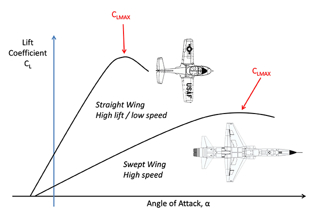
All of that reinforces with us as we train in simulators that the wing stops producing lift at stall warning and if we don't do anything about it, the nose is going to drop of its own accord, stick pusher notwithstanding. But this clearly isn't true for a swept wing aircraft, where the wing continues to produce lift well beyond CCLMAX as shown by the coefficient of lift graph. The T-38 I flew years ago did not have a stick pusher and when it stalled, the nose didn't pitch at all. (Your only indication was wing buffet and a plummeting VVI.)
In fact, a swept wing, T-tail airplane actually pitches up during the stall. (More on this at Stall Recovery.)
And all of this is the reason most modern swept wing, T-tailed jet aircraft are equipped with stick pushers: to make sure the angle of attack is reduced at or prior to CLMAX to give you an added margin over the aerodynamic stall. From this you may wish to take away a few points:
- Since you aren't allowed to practice the full stall in most aircraft or even simulators, it is critically important that you initiate the recovery when the stall warning system activates.
- If your stall warning system is inoperative and you venture into the stall, the nose of your aircraft may pitch up. You must reduce the angle of attack aggressively to break the stall.
- If you are in a Controlled Flight Into Terrain or Windshear escape maneuver in a swept wing aircraft, you still have more lift to extract from the wings after the stall warning at CLMAX.
2
Spins
Wing shape and stall onset
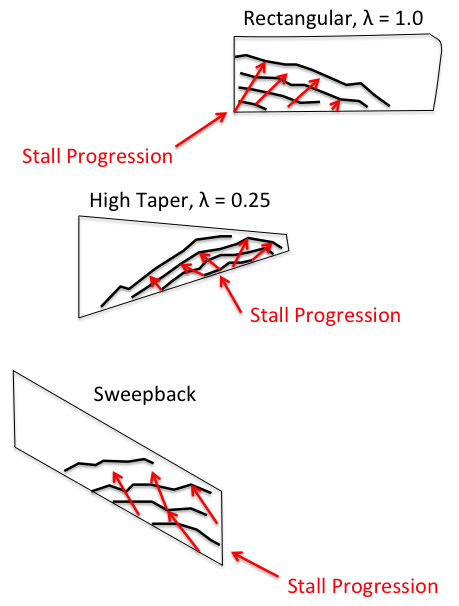
The first requirement for a spin is to be at or near an aerodynamic stall, the second requirement is for yaw. As we saw in How Wing Shape Affects Stall Warning and Roll Control, a stall begins at the roots for straight wing aircraft and at the tips for swept wing aircraft.
That means a straight wing aircraft has lots of warning that a stall is about to occur and continued aileron control to keep the aircraft in coordinated flight.
Conversely, a swept wing aircraft has less warning and once a stall is reached, less lateral control. A spin is more likely in a swept wing aircraft.
As we saw in the previous discussion about stalls, a swept wing, T-tail aircraft actually pitches up during a stall, making spin entry even more likely if the angle of attack isn't reduced immediately.
Spin Characteristics
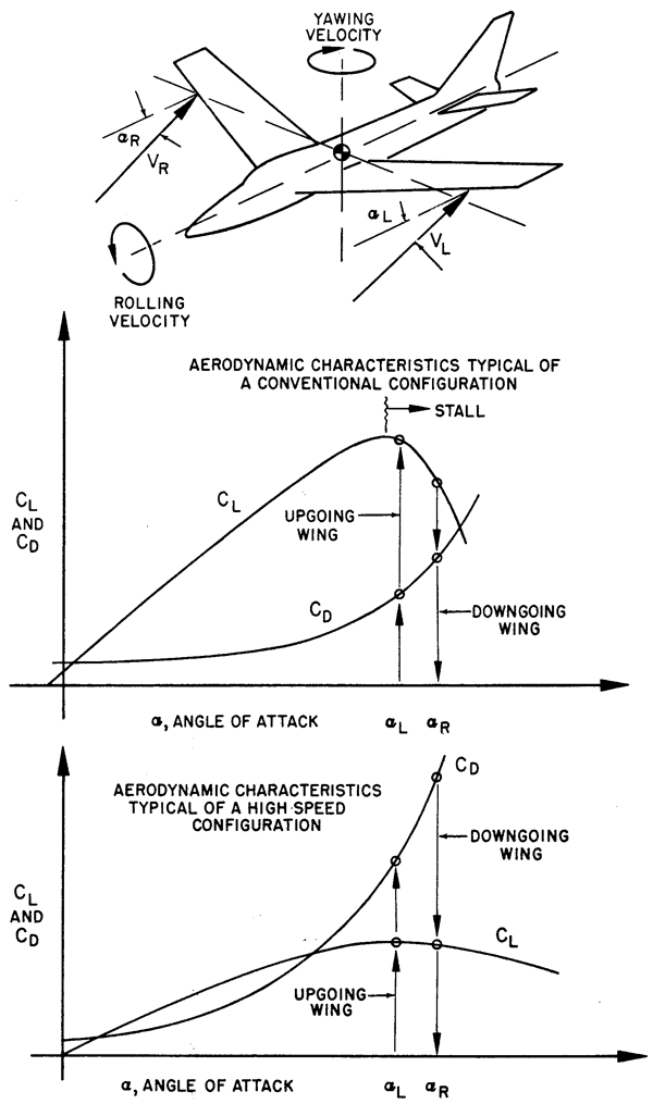
Hurt, pg. 310
The accompanying chart on top is for a straight wing aircraft ("conventional configuration"), and on bottom is for a swept wing aircraft ("high speed configuration").
The straight wing aircraft's spin is characterized primarily by the rolling motion with moderate yaw. The attitude of the spin is about 40° or more, nose down. In a straight wing aircraft, a stalled condition must exist before a spin can develop, but this is not true for a swept wing aircraft.
Source: Dole, pg. 149
The swept wing aircraft has CL and CD curves as shown [in the figure]. Note that the CL does not have a well-defined maximum lift point. When this type of aircraft is rolled at high angles of attack, only small changes in CL take place. There is no definite stall, and the wing autorotation contribution will be quite weak. The change in CD that occurs between the two wings, however, is substantial and a strong yawing moment is developed.
Modern, low aspect ratio, swept wing aircraft have the mass of the aircraft distributed along the longitudinal axis of the plane rather than in the wings. As the yaw develops, during the spin, this mass contributes to the inertial moments and tends to flatten the spin. This results in extremely high angles of attack and high sink rates.
Spin Recovery
To get out of a spin you must stop the rotation and lower the angle of attack. The problem in a straight wing aircraft is that your rudder and ailerons may be ineffective during the spin itself. The problem in a swept wing aircraft is that the gyrations may be so extreme that you may not have the time or ability to manipulate the controls quickly enough.
The U.S. Air Force once required all its pilots be well versed in spins and required its pilots master the "Single Spin Recovery" in the T-37:
- Throttles - Idle
- Rudder & Ailerons - Neutral
- Stick - Abruptly full aft & hold
- Rudder - Abruptly apply full rudder opposite spin direction (opposite turn needle) & hold
- Stick - Abruptly full forward 1 turn after applying rudder
- Controls - Neutral after spinning stops & recover from dive
The procedure is called the "Single Spin Recovery" because, in theory, it will get you out of any spin. We heard war stories of F-4 fighters and large bombers using the procedure to success.
3
High lift devices
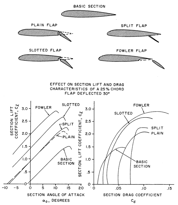
Hurt, pg. 40
We can increase the coefficient of lift of a wing by increasing its camber, decreasing the boundary layer separation, or by adding to the kinetic energy of the airflow above the wing:
- Camber Changers — The camber of the wing can be changed by adding leading or training edge flaps, slotted flaps, or slats to the wing. This, in effect, gives you a new wing on demand which produces more lift, albeit with an increase in drag.
- Boundary Layer Separation Control — The boundary layer can be made to remain closer to the wing by creating a thin layer of turbulence which increases the air friction. Vortex generators are a common method of achieving this. Another method is to introduce a vacuum over the top of the wing using holes with vacuum sources to pull the boundary layer in.
- Kinetic Energy Adders — The kinetic energy of the air above the wing can be increased by blowing air over the wing from an external source. A wing mounted engine with exhaust over the wing can achieve this.
For the purpose of this discussion, it will suffice to say these high lift devices serve to replace the existing coefficient of lift curves. In the case of trailing edge flaps, the new curves tend to the higher and displaced to the left, to lower angles of attack. To the pilot this means the angle of attack required for any given amount of lift is reduced.
4
Ground effect
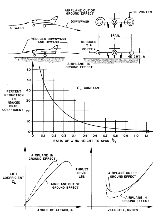
Hurt, pg. 380
As we saw in our discussion about Induced Drag, high pressure from the bottom of the wing spills over to the top from wing tip vortices. Because the aircraft is moving forward, this air spirals downward to depress the down wash of the wing and pulls the aerodynamic force of the wing aft. The aft component of aerodynamic force is induced drag.
The vortices spiral into a growing circle until they hit the fuselage, at which point they end. That is one-half of the wing span. So too, the vortices end as the aircraft nears the runway or any other ground or water surface. When this happens the deflection of the down wash decreases and therefore so does the induced drag.
A similar thing happens to the horizontal stabilizer on low tailed aircraft. As the tail enters ground effect it becomes more effective and may cause a nose-down pitching moment.
Ground Effect on Takeoff
When the aircraft is first rotated the wings are in ground effect. As the aircraft climbs to one-half the wing span, some aircraft may have a tendency to settle until more speed is developed. We could definitely notice this on older KC-135A aircraft at heavy weights. The tail can create a nose-up pitching moment when leaving ground effect. On lower power aircraft this can require the odd nose forward pitch input as the aircraft settles. On higher powered aircraft, such as the Boeing 747 or just about any Gulfstream, I've never noticed either issue on takeoff.
For more about this: Ground Effect.
Ground Effect on Landing
When the aircraft enters ground effect during landing, the decrease in induced drag means more of the aerodynamic force is directed parallel to the relative wind. The wing becomes more efficient and the aircraft may have a tendency to float. We noticed this in the Boeing 747, hence the need to "fly the airplane onto the runway" and the warning not to attempt to flare the aircraft to zero sink. A low tailed airplane may also experience a nose-down pitching moment.
An important ground effect impact is during a balked landing. Climbing out of ground effect can be problematic. More about this: Balked Landing
5
The region of reversed command
- The variation of power or thrust required with velocity defines the power settings necessary to maintain steady level flight at various airspeeds. To simplify the situation, a generality could be assumed that the airplane configuration and altitude define a variation of power setting required (jet thrust required or prop power required) versus velocity. This general variation of required power setting versus velocity is illustrated by the first graph of figure 6.2.
- This curve illustrates the fact that at low speeds near the stall or minimum control speed the power setting required for steady level flight is quite high. However, at low speeds, an increase in speed reduces the required power setting until some minimum value is reached at the conditions for maximum endurance. Increased speed beyond the conditions for maximum endurance will then increase the power setting required for steady level flight.
- REGIONS OF NORMAL AND REVERSED COMMAND. This typical variation of required power setting with speed allows a sort of terminology to be assigned to specific regimes of velocity. Speeds greater than the speed for maximum endurance require increasingly greater power settings to achieve steady, level flight. Since the normal command of flight assumes a higher power setting will achieve a greater speed, the regime of flight speeds greater than the speed for minimum required power setting is termed the "region of normal command. Obviously, parasite drag or parasite power predominates in this regime to produce the increased power setting required with increased velocity. Of course, the major items of airplane flight performance take place in the region of normal command.
- Flight speeds below the speed for maximum endurance produce required power settings which increase with a decrease in speed. Since the increase in required power setting with decreased velocity is contrary to the normal command of flight, the regime of flight speeds between the speed for minimum required power setting and the stall speed (or minimum control speed) is termed the "region of reversed command." In this regime of flight, a decrease in airspeed must be accompanied by an increased power setting in order to maintain steady flight. Obviously, induced drag or induced power required predominates in this regime to produce the increased power setting required with decreased velocity. One fact should be made clear about the region of reversed command: flight in the "reversed" region of command does not imply that a decreased power setting will bring about a higher airspeed or an increased power setting will produce a lower airspeed. To be sure, the primary control of airspeed is not the power setting. Flight in the region of reversed command only implies that a higher airspeed will require a lower power setting and a lower airspeed will requite a higher power setting to hold altitude.
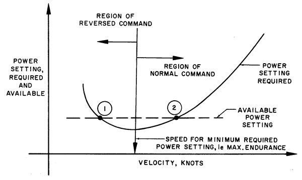
Hurt, pg. 354, figure 6.2
Source: Hurt, pp. 353-357
If you are in steady flight in the region of reversed command and pull the throttle back, you will decelerate. But if you want to stabilize at a new, lower speed, you will need more thrust at the lower speed than you did at the higher speed.
- Because of the variation of required power setting throughout the range of flight speeds, it is possible that one particular power setting may be capable of achieving steady, level flight at two different airspeeds. As shown on the first curve of figure 6.2, one given power setting would meet the power requirements and allow steady, level flight at both points 1 and 2. At speeds lower than point 2, a deficiency of power would exist and a rate of descent would be incurred. Similarly, at speeds greater than point 1, a deficiency of power would exist and the airplane would descend. The speed range between points 1 and 2 would provide an excess of power and climbing flight would be produced.
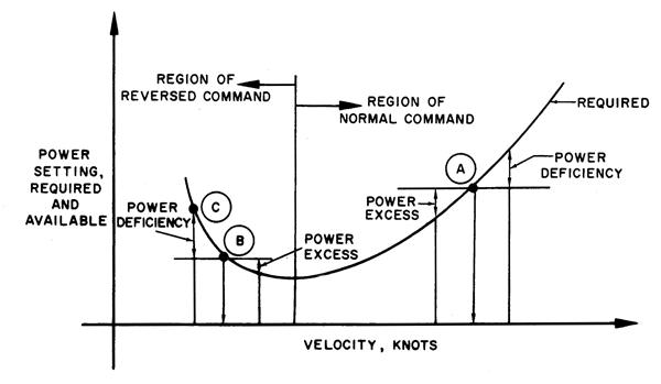
- FEATURES OF FLIGHT IN THE NORMAL AND REVERSED REGIONS OF COMMAND. The majority of all airplane flight is conducted in the region of normal command, e.g., cruise, climb, maneuvers, etc. The region of reversed command is encountered primarily in the low speed phases of flight during takeoff and landing. Because of the extensive low speed flight during carrier operations, the Naval Aviator will be more familiar with the region of reversed command than the ordinary pilot.
- The characteristics of flight in the region of normal command are illustrated at point A on the second curve of figure 6.2. If the airplane is established in steady, level flight at point A, lift is equal to weight and the power available is set equal to the power required. When the airplane is disturbed to some airspeed slightly greater than point A, a power deficiency exists and, when the airplane is disturbed to some airspeed slightly lower than point A, a power excess exists. This relationship provides a tendency for the airplane to return to the equilibrium of point A and resume the original flight condition following a disturbance. Also, the static longitudinal stability of the airplane tends to return the airplane to the original trimmed CL and velocity corresponding to this CL. The phugoid usually has most satisfactory qualities at low values of CL so the high speed of the region of normal command provides little tendency of the airplane's airspeed to vary or wander about.
- With all factors considered, flight in the region of normal command is characterized by a relatively strong tendency of the airplane to maintain the trim speed quite naturally. However, flight in the region of normal command can lead to some unusual and erroneous impressions regarding proper flying technique. For example, if the airplane is established at point A in steady level flight, a controlled increase in airspeed without a change in power setting will create a deficiency of power and cause the airplane to descend. Similarly, a controlled decrease in airspeed without a change in power setting will create an excess of power and cause the airplane to climb. This fact, coupled with the transient motion of the airplane when the angle of attack is changed rapidly, may lead to the impression that rate of climb and descent can be controlled by changes in angle of attack. While such is true in the region of normal command, for the conditions of steady flight, primary control of altitude remains the power setting and the primary control of airspeed remains the angle of attack. The impressions and habits that can be developed in the region of normal command can bring about disastrous consequences in the region of reversed command.
Hurt, pg. 354, figure 6.2
Source: Hurt, pp. 353-357
While this emphasis on AOA controls airspeed and thrust controls altitude is technically correct, it doesn't correspond to what a pilot sees and feels in the moment and I don't think it particularly relevant for this discussion.
- The characteristics of flight in the region of reversed command are illustrated at point B on the second curve of figure 6.2. If the airplane is established in steady, level flight at point B, lift is equal to weight and the power available is set equal to the power required. When the airplane is disturbed to some airspeed slightly greater than point B, an excess of power exists and, when the airplane is disturbed to some airspeed slightly lower than point B, a deficiency of power exists. This relationship is basically unstable because the variation of excess power to either side of point B tends to magnify any original disturbance. While the static longitudinal stability of the airplane tends to maintain the original trimmed CL and airspeed corresponding to that CL, the phugoid usually has the least satisfactory qualities at the high values of CL corresponding to low speed flight.
- When all factors are considered, flight in the region of reversed command is characterized by a relatively weak tendency of the airplane to maintain the trim speed naturally. In fact it is likely that the airplane will exhibit no inherent tendency to maintain the trim speed in this regime of flight. For this reason, the pilot must give particular attention to precise control of airspeed when operating in the low flight speeds of the region of reversed command.
- While flight in the region of normal command may create doubt as to the primary control of airspeed and altitude, operation in the region of reversed command should leave little doubt about proper flying techniques. For example, if the airplane is established at point B in level flight, a controlled increase in airspeed (by reducing angle qf attack) without change in power setting will create an excess of power at the higher airspeed and cause the airplane to climb. Also, a controlled decrease in airspeed (by increasing angle of attack) without a change of power setting will create a deficiency of power at the lower airspeed and cause the airplane to descend. This relationship should leave little doubt as to the primary control of airspeed and altitude.
- The transient conditions during the changes in airspeed in the region of reversed command are of interest from the standpoint of landing flare characteristics. Suppose the airplane is in steady flight at point B and the airplane angle of attack is increased to correspond with the value for the lower airspeed of point C (see fig. 6.2). The airplane would not instantaneously develop the lower speed and rate of descent common to point C but would approach the conditions of point C through some transient process depending on the airplane characteristics. If the airplane characteristics are low wing loading, high L/D, and high lift curve slope, the increase in angle of attack at point B will produce a transient motion in which curvature of the flight path demonstrates a definite flare. That is, the increase in angle of attack creates a momentary rate of climb (or reduction of rate of descent) which would be accompanied by a gradual loss of airspeed. Of course, the speed eventually decreases to point C, and the steady state rate of descent is achieved. If the airplane characteristics are high wing loading, low L/D, and low lift curve slope, the increase in angle of attack at point B may produce a transient motion in which the airplane does not flare. That is, the increase in angle of attack may produce such rapid reduction of airspeed and increase in rate of descent that the airplane may be incapable of a flaring flight path without an increase in power setting. Such characteristics may necessitate special landing techniques, particularly in the case of a flameout landing.
- Operation in the region of reversed command does not imply that great control difficulty and dangerous conditions will exist. However, flight in the region of reversed command does amplify any errors of basic flying technique. Hence, proper flying technique and precise control of the airplane are most necessary in the region of reversed command.
Source: Hurt, pp. 353-357
References
(Source material)
14 CFR 25, Title 14: Aeronautics and Space, Federal Aviation Administration, Department of Transportation
Dole, Charles E., Flight Theory and Aerodynamics, 1981, John Wiley & Sons, Inc, New York, NY, 1981.
Hurt, H. H., Jr., Aerodynamics for Naval Aviators, Skyhorse Publishing, Inc., New York NY, 2012.
Please note: Gulfstream Aerospace Corporation has no affiliation or connection whatsoever with this website, and Gulfstream does not review, endorse, or approve any of the content included on the site. As a result, Gulfstream is not responsible or liable for your use of any materials or information obtained from this site.