As a lifelong student, I'm often confronted with the fact that sometimes I don't have the necessary motivation to open the books or plunge through whatever material is presented to me. But unlike "college me," "pilot me" rarely has a choice in the matter. So how do I motivate myself? If you have the same issue, what methods can you employ to make studying something you want to do, not have to do?
— James Albright

Updated:
2023-04-15

(Shutterstock)
The problem gets amplified for a subject you've known for years but for which you have to maintain a high level of knowledge. If this sounds just like your regular aircraft recurrent training, that is exactly what I have in mind here. I am always "on the hunt" for a new technique. I present these in no particular order, since I quite often switch or combine methods. Variety, in fact, is the key here. I've had good success with all but one of these methods.
1 — The pre-study courseware plan
2 — The one month, comprehensive plan
3 — The "one button at a time" plan
4 — The "I am a mechanic now" plan

1
The pre-study courseware plan
The "Brand X" training company
Using the training vendor's pre-study courseware material has a severe drawback: most training vendors don't have pre-study courseware. For some vendors, it depends on the airplane. For my vendor of choice and my aircraft, we are given memory flash cards, pilot training books for avionics and systems, pilot study guide, and the initial training client guide.
- Memory flash cards
- Pilot training books for avionics and systems
- Pilot study guide
- Initial training guide
The flash cards are a bit simple and certainly not all inclusive. But they may represent what is expected of you, so I treat these as "musts" no matter which study method I've selected.
Some pilots use these as their primary references, since they don't have or trust their Airplane Flight Manual (AFM), Aircraft Operating Manual (AOM), or any other primary source materials. For these pilots, re-reading the vendor books can be a bit boring.
I normally use the manufacturer's guidance as primary and rarely look at the vendor's versions. For that reason, looking at the vendor's training books can be a useful change of pace for me, since I so rarely look at them.
For my aircraft, the pilot study guide is nothing more than a list of 466 questions.
If you think 466 is a bit much, you are right. Some of the questions are nothing more than technique. In my aircraft, for example, question number 290 is this: "Under what conditions will drag devices be required for descent?" The given answer is "WAI on and TAT < 0°C." Well a lot depends on the angle of descent, doesn't it?
While it can be tedious, I do like going through them now and then just to remind myself about something I had forgotten or to spur me on to further research.
I've been to some courses where the initial training guide was a poorly photocopied list of each day's events and nothing more. Fortunately, the initial training guide for my airplane is a 387 page masterpiece with a lot in it, but it is tailored for initial and not recurrent. There is, however, a very good recommended homework list. If you've ever shown up for recurrent thinking you knew less than you did after initial, this homework guide is a good way to fix that.
2
The one month, comprehensive plan
I normally get serious about recurrent 30 days ahead of time with a plan for each day. It is a seven step process that actually begins six months earlier:
- Starting the day after your last recurrent: stay in the books!
- Starting one month prior to recurrent: (re)learn aircraft limitations every day until recurrent
- Starting four weeks prior: study one aircraft system each day for two weeks
- Starting three weeks prior: review one procedure each day for two weeks
- Starting one week prior: pick a theme to review each day
- Step 6: The day before class: review simulator prep materials
- Step 7: The day after recurrent: "After action report"
More about the one-month plan: Preparing for Recurrent.
3
The "one button at a time" plan
Switch 1
My Airline Transport Rating check ride was in a United Airlines Boeing 747 and was administered by two FAA check airmen who were assigned to keep an eye on UAL. The oral was given by Inspector J. McDougall, a humorless man who had a reputation for giving four hour orals. We sat down in a briefing room where one wall was dedicated to a large poster of the pilots’ panels and a side wall to the flight engineer panel. I had many hours in that room, facing the pilots’ panels. Inspector McDougall pointed to the battery switch on the engineer’s panel and said, “How does this switch relate to the rest of the airplane, don’t leave anything out.” I spoke for an hour and a half and concluded with, “and that’s how the battery switch relates to everything else on the airplane.” He got up, signed my paperwork, and started to leave. I said, “that’s it?” He said, “you covered everything, I don’t have any other questions for you.”
Over the years I’ve come up with a variety of methods of studying aircraft systems to keep things interesting and sooner or later end up with a look at “Switch 1” in the aircraft and then research everything I can in relation to that switch. In the Gulfstream GVII, the first switch you press before going to fly is the “Arm” switch on the Emergency Power panel.
The Airplane Power-up Checklist
That checklist is in the Airplane Flight Manual (AFM), Section 02-02-10:
- EMERGENCY POWER . . . ARM/Check+
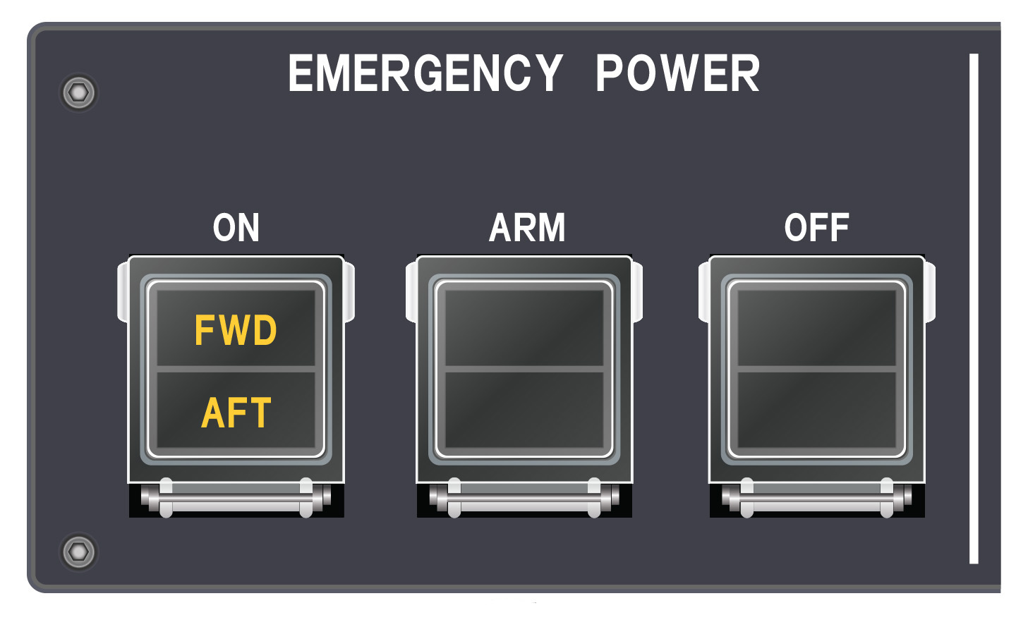
Pressing the “ARM” button causes the Emergency Power system to arm, at which time it discovers that ESS DC < 20V, which in turn causes the Emergency Power system to turn on.
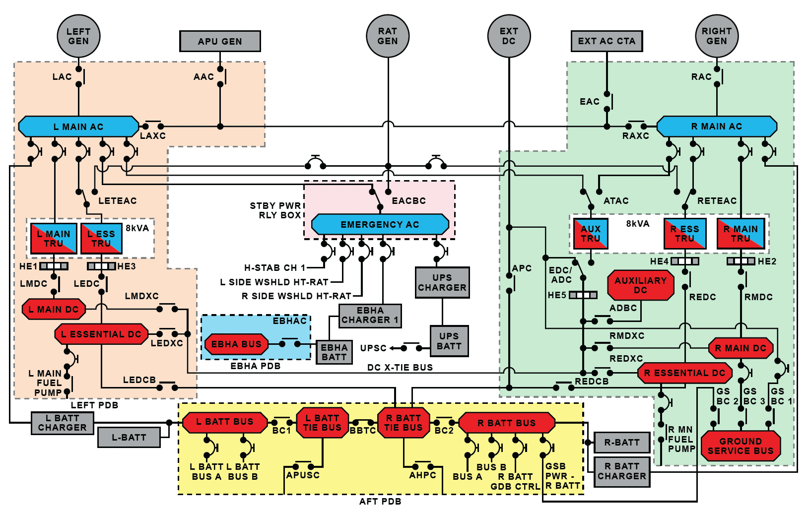
The Left Essential DC (L ESS DC) and Right Essential DC (R ESS DC) busses are normally powered by their respective Essential Transformer Rectifier Units (TRU) which are normally powered by their respective Main AC busses. Alternatively, the L ESS DC and R ESS DC busses can be powered by either the left (L BATT) or right (R BATT) batteries. In the case of a completely unpowered aircraft, pressing the ARM button on the Emergency Power Panel arms the Emergency Batteries. Once armed, the batteries check for at least 20 V at both essential DC busses. Since these busses are unpowered, the emergency batteries switch on.
It takes a few seconds for the displays to come up, so use that time to look back for evidence the emergency lighting is up, then forward to see two displays on the glareshield and two more near the throttle quadrant.
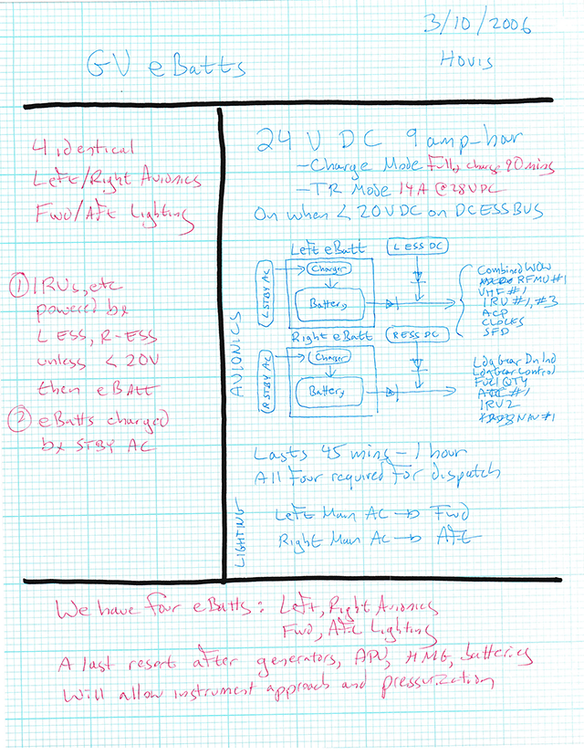
About the emergency batteries
- Each emergency battery is a lead acid unit with an internal charger and is rated at 24V, 10.5 amp/hr. [PAS p. 4-10]
- The forward E-Batt is in the LEER, the aft E-Batt is in the Fwd BEER. [PAS p. 4-10]
- The E-Batt / charger can be in:
- Charge mode where it takes 1.5 hours to fully charge; the Fwd E-Batt is charged by LMAIN AC, the Aft E-Batt is charged by RMAIN AC. [PAS p. 4-10]
- TR mode where it provides 14 amp/hr 24 V. [PAS p. 4-10]
- Discharge mode where it provides about 45 mins of power for emergency lighting, SFDs, IRUs, VHF 1, TSCs #2 and #3, and opening Fwd MED. [PAS p. 4-10]
- Armed E-Batts activate when L or R ESS DC < 20V or anytime a break power transfer occurs; will produced Fwd or Aft Emer Battery On CAS messages. [PAS p. 4-10]
- If the Emergency Power system is off, the ARM and OFF switches will be illuminated. [PAS p. 4-38]
- If the Emergency Power system is armed and the ESS DC Bus > 20V, all the switch legends will be off. [PAS p. 4-38]
- The Emergency Power system can be activated in two ways: by depressing the ON switch or if the L or R ESS DC < 20V with the system armed; if activated, the ON capsules illuminate. [PAS p. 4-39]
- Emergency power will illuminate the cabin aisle lights [PAS p. 11-37]
- Emergency power will illuminate the airstair lights [PAS p. 14-29]
- Emergency power will bring up the Backup Engine page on TSC 2 and TSC 3 [PAS p. 11-37]
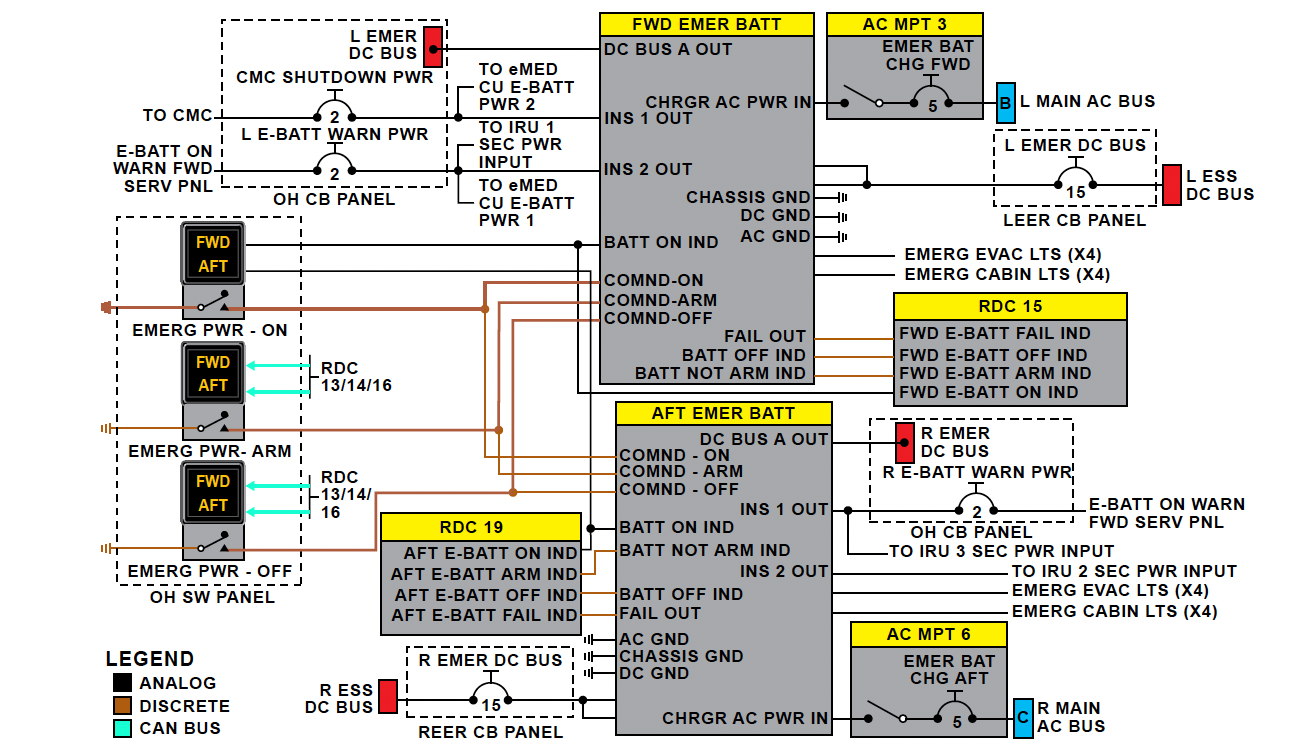
In normal operation, the EBP will be armed with the essential DC busses powered. Under these conditions, the EBP solid state power output control function allows up to 15 amps from the onside ESS DC Bus 28 V power input to pass through and power respective L / R Emergency DC Bus. The L Main AC Bus B phase provides power for the FWD EBP integral charger to keep the EBP battery charged (Figure 24-10). The R Main AC Bus C phase is used to charge the Aft EBP. [FSI MTM, Sect ATA 24]
If switched ON or triggered to ON from the armed condition, each emergency battery:
- Provides 24 VDC 15 amp to its respective emergency DC bus.
- Provides up 4 amps to five outputs for emergency lights.
- Provides 5 amps un-switched to outputs labeled INS 1 / 2:
- In the FWD EBP, the INS 1 output is used during CMC normal power-down and the INS-2 output is used to power IRU 1 if its normal power input is lost. This output also illuminates a warning light in the Fwd Service Switch Panel when the IRUs are powered by EBP. Both of these outputs are also used for unlocking the eMED actuators if no other power source is available. [FSI MTM, Sect ATA 24]
- The AFT EBP INS 1 output is provided to IRU 3 and INS 2 to IRU 2. Both outputs are also provided to the warning light in the Fwd Service Switch Panel. [FSI MTM, Sect ATA 24]
- The EBP ON output to illuminate the ON switch annunciator is also provided to the RDCs. This signal will be provided to the modular avionics units (MAU) 1 and 2 for generation of the respective advisory CAS message.
When the FWD EBP is discharging, the L ESS DC will power:
- ATC 1 – refers to Transponder 1, which is the power-up selection. You can change to ATC 2 using the TSC / ATC / Traffic page. If ATC 1 fails, ATC 2 is automatically selected. (Symmetry 2B-23-00, p. 23]
- ELT – refers to the Emergency Locator Transmitter which is in the baggage compartment water supply closet, orange in color. The ELT switch in forward of the copilot’s sidestick and has two positions. ON activates the ELT transmitter, turns on a red light near the switch, and generates a cyan CAS “ELT Transmitting” message. ARM makes the ELT ready. It can be reset by moving it from ARM to ON for 1 second and then back to ARM. When activated, it transmits on 406 MHz for 24 hours, and then on 121.5 and 243.0 until the battery is depleted. (PAS 2-51)
- AHRS1 – refers to Attitude Heading Reference System 1, which provides inputs to SFD1 and to the Flight Control Computers. The AHR Units are comprised of three gyros, three accelerometers, and a computer. (FSI MTM ATA 34)
- MAG1 – refers to the Magnetometer1, which is used for heading reference by the AHRS and is located on the left side of the vertical fin, just below the VOR/LOC antenna. (FSI MTM ATA 34)
- MRC1 – refers to Modular Radio Cabinet, which is located in the LEER and includes COM1, VOR receiver, LOC receiver, GS receiver, Marker Beacon receiver, VHF Data Broadcast (VDB) receiver, and GPS receiver), XPDR1, DME1, ADF1, and NIM1. (FSI MTM ATA 34)
- NIM 1 – refers to Network Interface Module 1, which is used to connect MRC1 equipment to NAV1 via the Avionics Standard Communications Bus (ASCB).
- NAV 1
- Crew Audio Unit 1 is a microprocessor located under the pilot’s floorboards used to covert digitized audio from the NIMs to analog signals for the headphones and speakers.
- STBY Flight Display 1
- TSC 2
- CCD 1
- VHF 1
- Emergency Lights
When the AFT EBP is discharging the R ESS DC will power:
- TSC 3
- Crew Audio Unit 2 is a microprocessor located under the copilot’s floorboards, used to covert digitized audio from the NIMs to analog signals for the headphones and speakers.
- STBY Flight Display 2
- AHRS 2 – refers to Attitude Heading Reference System 2, which provides inputs to SFD2 and to the Flight Control Computers. The AHR Units are comprised of three gyros, three accelerometers, and a computer. (FSI MTM ATA 34)
- MAG 2 – refers to the Magnetometer2, which is used for heading reference by the AHRS and is located on the right side of the vertical fin, just below the VOR/LOC antenna. (FSI MTM ATA 34)
- LDG Gear Dump Valves
- CCD 2
- Crew Audio Unit 3 is a microprocessor located forward of the center pedestal under DUs 2 and 3, used to covert digitized audio from the NIMs to analog signals for the headphones and speakers.
The emergency power functional check
The “Check+” in the power-up checklist refers to the Operating Manual (OM), Section 01-10-40:
- EMERGENCY POWER . . . ARM
- Emergency Lighting . . . Verify powered
- SFDs (2) . . . Verify powered
- TSC 2 and TSC 3 . . . Verify powered
The emergency lighting includes:
- 3 over wing light assemblies on each wing mounted below the windows, each with a forward light powered by the FWD Emergency Battery and an aft light powered by the AFT Emergency Battery.
- 1 under wing light.
- 2 exit signs, mounted between each pair of emergency exit windows.
- Aisle lighting
- A vestibule light
- A main entry door light

Next up?
This brief examination of a single switch in the cockpit managed to explore more than just its small part of the electrical system and sparked a look into a few systems where my knowledge was lacking. It left me with a question about “NAV 1” beyond the TSC menu selections. Perhaps my look at “Switch 2” will answer that question.
4
The "I am a mechanic now" plan
For some aircraft, pilots are only given enough information to have a very broad idea of systems while mechanics are given a more complete picture. Studying the maintenance manual can help pilots better understand systems as well as provide another take.
In the Gulfstream GVII, for example, we pilots know that our Integrated Drive Generators (IDGs) are oil cooled. The only reference we have to that in our manuals is in a manual called "Production Aircraft Systems" (PAS), page 4-2:
- Oil cooled generator
- 40 kVA, 115 VAC, 400 Hz, 3 Phase
So we know the generator is cooled by oil, but not much else. The maintenance manual suite includes something called the System Description Manual (SDM), where we see this §24-00-00:
1.3.3.1.2 Integrated Drive Generator Oil Cooler
The IDG oil cooling system components include the heat exchanger (cooler), oil filter, bypass valves, interconnecting tubing and fittings. The oil in the IDG is kept in the specified operating temperature range by a surface fin-type air-oil heat exchanger (oil cooler) and is filtered before the oil enters the oil cooler. The cooler is located in the engine bypass duct and is connected to the IDG oil-in and oil-out ports with oil lines.
The oil cooler contains a pressure relief valve that protects the cooler from over pressurization and is set at a nominal 50 psid. During bypass operation, two thirds of the cooler is bypassed.
The external cooling system provides a pressure drop of 90 psid maximum during normal operation and decongeals without causing an IDG over temperature during starting conditions. The normal external system limits for the IDG oil in temperature is 150 - 200°F (65.5 - 93°C) and normal oil out temperature is 168 - 221°F (75.5 - 105°C).
The oil heated during operation is pumped from the IDG through a scavenge filter to the external oil circuit. The heat is removed from the oil circuit as it flows through the oil coolers. The cooled oil is then returned to the IDG and circulated through the IDG hydraulic circuit by the charge pump inside the IDG.
The oil supply system purpose is to provide the IDG with pressurized lubrication and cooling oil during operation. The pressurized oil is also used to control the rotation speed of the generator through the Constant-Speed Drive (CSD).
The charge relief valve located on the IDG input housing is provided to depressurize the IDG when the vent valve is pushed prior to oil servicing or other maintenance. This prevents oil spray when the pressurized system is opened.
This is a spring-actuated valve designed to maintain internal pressure in the housing. A biasing spring, which acts on a piston, closes the vent valve allowing the air pressure build up in the IDG case. Normal charge pressure is regulated at 240 - 280 psi.
The externally cooled lubrication oil enters the IDG through the oil-in port and flows to the generator, pump, motors, servo valve, control piston and lubricating system.
A differential pressure indicator, located in the IDG scavenge oil system, senses pressure upstream and downstream of the filter element. The indicator housing contains a spring-loaded, pop-out button, which is held in place by a magnet during normal operation. When the pressure drop across the filter is greater than the spring force (>60 psid), the magnet is forced away from the indicator button allowing the pop-out button to extend providing a visual indication of a clogged filter. A temperature lockout feature is incorporated to prevent a false pressure differential indication during startup with cold oil. This is done by a bimetal element that locks the pop-out button in place during low temperature operation but expands to permit actuation during the normal operating temperature range if the filter becomes clogged.
5
The "find a student" plan

I learned early on that the best way to learn is to teach. The act of preparing the lesson encourages you to dive deeper and ensure what you teach is accurate. Having students learn from you provides feedback. Is what you are teaching accurate? Are you explaining it correctly?
If you are in a flight department, your fellow pilots might welcome an in-house lesson. (Especially if someone else volunteers to do it.) In my flight department, if things are slow, we plan on having our pilots take turns so that at least one lesson is presented at each monthly meeting.
Another avenue is to publish your notes. You can find a lot of my Gulfstream G450 and G500 notes here: www.code450.com. You will also find notes from Steven Foltz and Ivan Luciani. Their notes and mine combine to present information for the Gulfstream G450, G500, G550, G600, and G650. You can contact the webmasters at Code 450 if you want to contribute.
6
The "I wrote these notes for a reason" plan
One of my last, pre-computerized notes
For most of us, our initial training and recurrent notes never survive the six months between training periods. If you learn to take notes effectively, they can become a great resource of future studies. Learn how: Note Taking.
Most of my notes these days are computerized and you will find those from my previous aircraft here: www.code450.com. A list of computerized notes need not be anything more than a Word document. Here are some examples from my GVII initial. Note: these notes are from 2019, so they might be out of date.
- Use the AFM to go from a dark cockpit to when the DUs are powered, then transition to the ECL.
- Umbrella CAS messages are presented in lieu of two or more messages that have a common cause. This helps to identify the root cause and declutter the CAS.
- Some Consequential Alerts (CAs) are presented and some are not. To be displayed: (1) Must be directive. (2) Must reduced the flight envelope. (3) Must degrade the flight envelope. (4) Must degrade ECS or CPCS. (5) Must result in loss of further annunciations or alerts. (6) Must impact AOG status.
- Certain CAS messages are filtered during certain "on ground" conditions. These may be for systems that are not powered or are waiting for systems that are not powered because of electrical loads or engines not running.
- Certain CAS messages are filtered base of flight parameters. These filters can be canceled when WOW transitions back to G, altitude exceeds 400' AGL, or speed < 60 knots.
- Low speed takeoff: WOW = G, TLA > 22°, speed > 60 knots
- High speed takeoff: WOW = G, TLA > 22°, speed > V1-5 knots
- Landing: RA < 400 AGL, flap handle > 25
- This is a "CAS driven" airplane. Recommended for each abnormal or emergency procedure:
- Verify CAS
- Check synoptic
- Identify AFM procedure
- Approaches: review approach chart, identify arrival quadrant, find IAF best match, program DANA (Destination, Arrival, Nav, Altitude).
- Predictive windshear. Radar looks into weather ahead, EGPWS alerts when actually in windshear.
- Low speed awareness. VMIN normally occurs 5 knots before yellow band. Block 1 aircraft will engage autothrottles regardless of autopilot status and will maintain VMIN. Once in yellow band for 2-3 seconds, "Airspeed Low" in HUD and aural alert every five seconds. You can maneuver, but the yellow band will contract and red band will increase as wing loading is increased.
- "Eng Fail (U)" means FADEC detects a failure that cannot be restarted, "Eng Out (U)" means engine not running with fuel control in RUN position, a restart may be possible. In this case, when fuel control moved to RUN, "Eng Out (U)" message replaced "Assisted Start Envelope" or "Windmill Start Envelope" messages.
- An uncommanded engine shutdown results in a break power transfer. You will need to check for a loss of selected flight guidance, uncommanded change in altimeter setting, loss of automation.
- WAI and CAI come on automatically if in auto, > 400' AGL, < FL 350. WAI attempts to maintain 130°F. Stab is not heated.
- Autobrakes RTO armed only on the ground, enabled when greater than 60 knots, activates when throttles reduced to idle, applies 600 psi braking if wheel speed between 60 and 80 knots, maximum antiskid braking if faster.
- Autobrakes landing mode active with MLG Ground WOW and wheel speed > 60 knots, initially apply to assist in de-rotation, activates with NLG Ground WOW. LOW mode ramps up to 7 feet/sec2 over 3 seconds. MED ramps up to 10 feet/sec2 over 3 seconds. HIGH mode gives you maximum antiskid braking, the PAS seems to say it is also ramped up over 3 seconds.
Here are my notes from my first GVII recurrent:
- The engine fire handle clicks when activated, so that's a clue when fire notification is filtered.
- GAC test director says Type IV developmental testing is done, waiting for "concurrent" testing, which means testing with FAA on board.
- If you hit TO/GA during an ILS or RNAV, you are done (you are going around), cannot recover expeditiously.
- Use of the "Inhibit" switch is prohibited inflight. The only reason it is on the aircraft is they couldn't get CAS filtering testing complete prior to initial certification.
- If you load any published procedure with an altitude higher than your cruise altitude, the system can change your cruise altitude without telling you.
- Pre Windshear replaces increasing performance windshear.
- Use the boresight during a windshear recovery, not the FPV (which moves too erratically for precise control.
- Nav lights are steady when okay, flashing when one of the LED sets has failed.
- To service oil you need the ground service bus on (to check) and main batteries on (to use the pump).
- The ignition channels change with the run switch from off to on and a flight cycle.
- Drift down information: OM, Perf, General.
- External battery switch powers both essentials and the lower beacon.
- The engine driven hydraulic pumps need 8% N2 on the ground, 58% inflight to work.
- Extra hydraulics: PTU "picks tires up" and the AUX gives you everything you need to land.
- The stick shaker only goes off with lateral pulls; if you pull without lateral input, the nose lowers itself.
- QATAR took off high, hot, heavy; resulted in low speed awareness, causes "airspeed low," may start using F10 as standard takeoff setting.
- High Incidence Angle Protection Function (0 Flap) a subfunction of normal control law. Under certain conditions, FCCs are programmed to consider wings contaminated, such as at 0 flap and WAI off. Reduces angle required to get PLI, stick shaker, etc.
- Gyroscopic precession is the reason the nose wheel is snubbed, not the tire.
- 8th stage bleed pressures
- 14 psi - normal
- 24 psi - low power, ground ops
- 34 psi - single pack ops below 40,000'
- 22 psi - single pack ops above 40,000'
- PACK = Pneumatic Air Conditioning Kit
- Ozone filter is filled with platinum
- All three TROV motors are DC
- The reason we pressurize to 0.3 PSID is to facilitate ground evacuation.
Photo from class
While there are some good nuggets here, most of it makes for poor study material.
7
The "I'm too good for this" plan
A final method must be mentioned: no preparation at all. I must admit I was forced to try this a few times because I was so busy flying I didn't have time to prepare. And I suppose some personal laziness might be to blame too. This method usually fails. Even when things turn out okay, the results have to be classified as opportunities lost. As well as you may have done, you could have done much better.