Not too long ago, pilots were taught two types of instrument approaches. The first, called “precision,” had a glide slope and once the final descent was begun, it was continued all the way to the touchdown zone. The second, called “non-precision,” required pilots descend smartly to get under a cloud deck, level off at the Minimum Descent Altitude (MDA), look for the runway, evaluate when to descend, and then change thrust, pitch, and trim to establish a glide path with just a few seconds to go. There were a lot of ways to mess up.
— James Albright

Updated:
2024-04-01
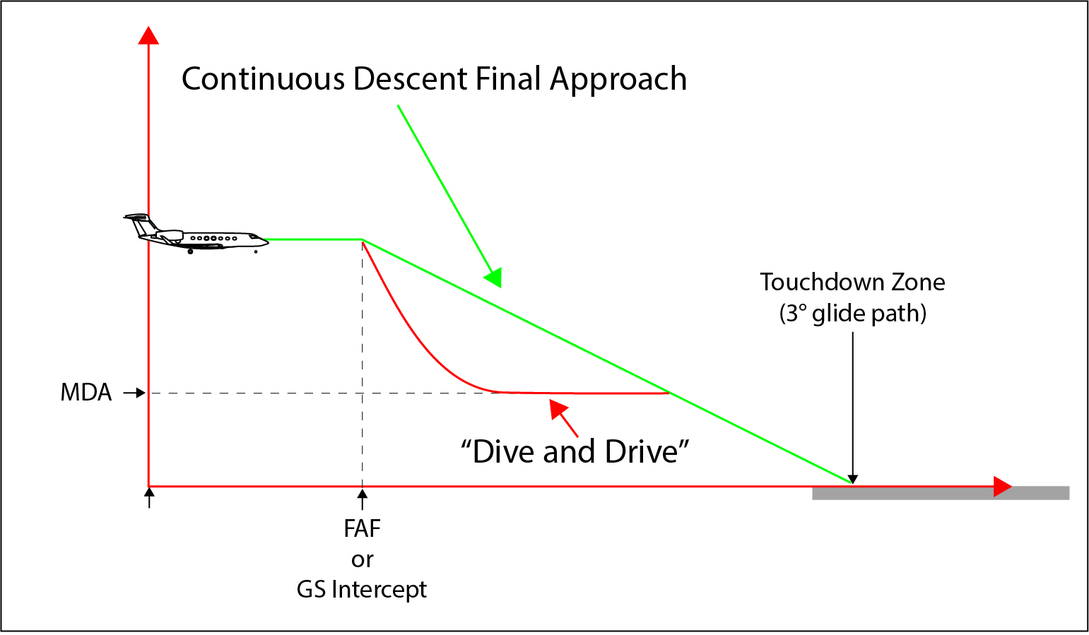
CDFA versus "Dive and Drive" (my drawing)
Flying a Continuous Descent Final Approach (CDFA) eliminates the MDA level off, puts the airplane in a position to land when the runway is sighted, and forces you to go around if the runway is not sighted before a normal visual descent point. It is easier to fly than a dive and drive approach and you don't need any special equipment. But technology does help.
Note: The examples in this article are more than likely out of date but are used to illustrate the CDFA process. Many countries are adopting the CDFA technique and making changes as they fine tune.
4 — Do you need special equipment?
5 — What kind of approach is suitable for CDFA?
6 — Computing a Vertical Descent Angle (VDA)
7 — Computing a vertical descent rate

1
CDFA defined
A continuous descent final approach is what you do for every straight-in ILS and what you attempt to do for every visual straight-in: you hit the glide path and start down on an angle that ends up in the touchdown zone of the runway. You can also do this when in instrument conditions flying a non-precision approach, which we should probably call an "approach without vertical guidance."
CDFA is a technique for flying the FAS [Final Approach Segment] of a NPA [Nonprecision Approach] as a continuous descent. The technique is consistent with stabilized approach procedures and has no level off. A CDFA starts from an altitude/height at or above the FAF [Final Approach Fix] and proceeds to an altitude/height approximately 50 ft (15 meters) above the landing runway threshold or to a point where the type of aircraft will begin the flare maneuver.
Source: Source: AC 120-108A, §2.4
CDFA: a technique, consistent with stabilized approach procedures, for flying the final approach segment of a non-precision instrument approach procedure as a continuous descent, without level-off, from an altitude/height at or above the final approach fix altitude/height to a point approximately 15 m (50 ft) above the landing runway threshold or the point where the flare manoeuvre should begin for the type of aircraft flown.
Source: ICAO Doc 8168, Vol I, Ch. 1, Definitions
2
Why is it needed?
Flying an approach without vertical guidance can be an invitation to making fatal mistakes. Even with the best technology, flying a “dive and drive” approach can be a problem.
Failure to level off
We often pull the throttles and head down from the final approach fix at 1,000 feet per minute or more, knowing we have to level off at the MDA. But spotting the runway prior to the MDA can cause pilots to forget they are not headed vertically to the runway, but short of it. See: Corporate Airlines 5966 Case Study.
Failure to maintain the MDA until in position to land
Even if you level off at the MDA, you need to keep the airplane there until the runway is spotted and the airplane is in a position to land. See: American Airlines 1572 Case Study.
Failure to wait at the MDA until in a position to land
In a low visibility approach, we can't always perceive the angle to the runway and it can be tempting to push the nose over the minute we see the runway. But if you do this too early you don't have a good idea of the descent rate required or you could lose sight of the runway. See: Crossair 3597 Case Study.
Failure to go around if the runway is spotted too late
If you are level at the MDA you should have an idea of where you will intercept a normal glide path to the touchdown zone. Once you've passed this point, you really ought to go missed approach. You could be tempted to try the landing, not really knowing how much pavement you have ahead of you. I have a case study of sorts for this one, but it is a bit personal.
Sometime in 2006 I was a recently qualified pilot in a Gulfstream GV, though I had thousands of hours of experience in other Gulfstreams and had flown hundreds of approaches in weather at or near minimums. I was in the right seat, monitoring my boss’s approach to a short runway flying a non-precision approach. At the time I didn’t know he had a desire to hand fly all approaches and a tendency to drift from altitude, both high and low, while at MDA. I say this as preamble, but it in no way excuses my failure to say “go around” when I realized what was happening.
The terrain around the airport was flat, but I announced that the captain was deviating below the MDA. He responded, “correcting” and he appeared to do so. As we passed the visual descent point, the point from which a normal descent to landing could be made, I assumed he would continue to the MAP and then go around. I diverted my eyes to the approach plate, which was clipped to the yoke in front of me, and got ready for my go around duties, which were considerable in that airplane back then. (Gulfstream since greatly simplified the procedure.)
I felt the nose pitch over and to my surprise I saw the runway. Not the approach lights, which at that point were behind us. I was speechless and in a second we were on the runway with the captain hard on the brakes and thrust reversers. He managed to stop us with about a hundred feet remaining.
At this point in my career, I had been flying jet aircraft for 27 years and never seen anyone do this before. I feel certain that had I stayed head up I would have ordered a go around when the captain spotted the runway. But I am far less certain that he would have obeyed.
3
Is CDFA required?
Many countries do require CDFA, but the application of the technique is not consistent. Some countries list a CDFA approach with "CDFA" in the minimums section while others use "DA" or "DA/MDA" to signify such approaches. The only way to ensure you are following the rules of the host nation is to look it up in the country's Aeronautical Information Publication.
ICAO preferred technique
Studies have shown that the risk of controlled flight into terrain (CFIT) is high on non-precision approaches. While the procedures themselves are not inherently unsafe, the use of the traditional step down descent technique for flying non-precision approaches is prone to error, and is therefore discouraged. Operators should reduce this risk by emphasizing training and standardization in vertical path control on non-precision approach procedures. Operators typically employ one of three techniques for vertical path control on non-precision approaches:
- continuous descent final approach (CDFA);
- constant angle descent; and
- step down approach.
Of these techniques, the CDFA technique is preferred. Operators should use the CDFA technique whenever possible as it adds to the safety of the approach operation by reducing pilot workload and by lessening the possibility of error in flying the approach.
Source: ICAO Doc 8168, Vol I, ¶ 1.8.1.1
EU required
Approach flight technique — aeroplanes
All approaches shall be flown as stabilised approaches unless otherwise approved by the competent authority for a particular approach to a particular runway.
Non-precision approaches
(1) The continuous descent final approach (CDFA) technique shall be used for all non-precision approaches.
(2) Notwithstanding (1), another approach flight technique may be used for a particular approach/runway combination if approved by the competent authority. In such cases, the applicable minimum runway visual range (RVR):
(i) shall be increased by 200 m for category A and B aeroplanes and by 400 m for category C and D aeroplanes;
(ii) for aerodromes where there is a public interest to maintain current operations and the CDFA technique cannot be applied, shall be established and regularly reviewed by the competent authority taking into account the operator’s experience, training programme and flight crew qualification.
Source: EASA Air Operations, ¶CAT.OP.MPA.115
Required by some countries
Many Contracting States require the use of the CDFA technique and apply increased visibility or RVR requirements when the technique is not used.
Source: ICAO Doc 8168, Vol I, ¶ 1.8.2.1
United States recommended
The FAA recommends accomplishing a CDFA on all of the following published NPAs:
- VOR;
- VOR/DME;
- NDB;
- NDB/DME;
- LOC, LOC BC;
- LOC/DME;
- Localizer type directional aid (LDA);
- LDA/DME;
- SDF;
- SDF/DME;
- RNAV (GPS) LNAV line-of-minima;
- RNAV (GPS) LP line-of-minima; and
- Tactical Air Navigation System (TACAN).
Source: AC 120-108A, §2.6
4
Do you need special equipment?
A CDFA does not require specific aircraft equipment; however, the aircraft must be equipped to accomplish the NPA procedure. Pilots can safely fly NPAs with a CDFA using basic piloting techniques, aircraft flight management systems (FMS), or RNAV systems. Pilots can use points defined by a DME fix, crossing radial, GPS distance from the runway, etc., on the approach plate to track their progress along both the lateral and vertical approach paths to the MAP.
Source: AC 120-108A, §3.1
5
What kind of approach is suitable for CDFA?
A CDFA may be flown on any NPA. There are no specific approach requirements nor any requirement for a vertical descent angle (VDA), glide path (GP), or visual descent point (VDP) to be published on an IAP in order to fly a CDFA. However, the use of a published VDA or a GP with a published or derived VDP on the IAP can help pilots calculate a desired rate of descent. This rate of descent may be flown by using the aircraft’s Vertical Velocity Indicator (VVI).
Source: AC 120-108A, §3.2
I think there are at least three exceptions to the “CDFA may be flown on any NPA” statement: circling approaches, approaches with close-in obstacle considerations, and steep approaches.
Close-in obstacle exception
When an approach is published without a VDA, Flight Inspection Services (FIS) has previously determined that a VDA should not be published due to obstacles. Flying the VDA below the MDA might not provide acceptable obstacle clearance. The VDA will not be published and a chart profile note reading “Visual Segment – Obstacles” should be published on the TPP IAP. Operators may still calculate and fly a CDFA to the runway, but, if doing so, must not descend below the MDA without visual requirements (refer to part 91, § 91.175). Once passing the MDA into the visual segment of the IAP, operators must see and avoid all obstacles.
Source: AC 120-108A, §3.3.2
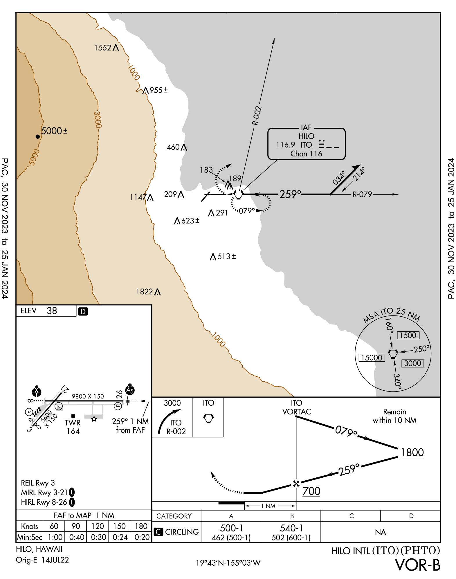
Extract of PHTO VOR/DME-A (FAA chart)
The Hilo Airport, HI (PHTO) VOR-B provides an example where a straight-in CDFA appears possible, but close-in obstacles make preclude it.
Circling approach exception
A circling approach at minimums will usually require a turn to final inside stable approach criteria, though it shouldn’t. See: Circling Good Riddance! But any circling approach that isn’t aligned with the landing runway is not a good candidate for a CDFA. Flying a CDFA to the approach runway may not be the wisest course of action when you are trying to acquire the airport environment in time to maneuver to a different runway.
Steep approach exception
Even an approach that appears to be aligned with the runway may not be a good candidate for a CDFA if the required descent is too steep. Many Colorado mountain airports, for example, have approaches that are aligned with the runway but required excessive descent angles to fly when aligned with the approach course.
6
Computing a Vertical Descent Angle (VDA)
From the approach chart
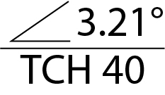
VDA symbol
U.S. FAA approach plates display the VDA using the symbol shown below. Other approach plate types may use similar methods to indicate VDAs.
Manually computing VDA
If the approach plate does not provide the VDA, you can compute your own, even without a scientific calculator. If you have such a calculator, the formula is:
You can approximate the VDA with this simplified formula:
Take, for example, the RNAV(GPS) Rwy 17 at Concord Municipal Airport, NH (KCON). The FAF is at 2300 and is 6 nm from the runway. The runway elevation is 342, and the TCH is 50. Using the two methods:
and:
If your avionics allow you to set a vertical angle passing the FAF, the VDA will start you down on a CDFA. If your avionics only provide for a vertical descent rate, you can compute that too, as shown below.
Maximum Vertical Descent Angles (VDAs)
A VDA is calculated from the FAF altitude to the threshold crossing height (TCH) altitude. It is published on the IAP with the VDA symbol. The optimum VDA is 3.0°. The minimum VDA is 2.75°. Table 3-1 below provides the maximum VDAs for different aircraft categories.
Source: AC 120-108A, §3.3
| CAT | Maximum Angle |
|---|---|
| A (80 knots or less) | 6.40 |
| A (81-90 knots) | 5.70 |
| B | 4.20 |
| C | 3.77 |
| D | 3.50 |
| E | 3.10* |
* United States Air Force (USAF)/United States Navy (USN) Category (CAT) E maximum is 3.5°
Table 3-1. Maximum VDAs (AC 120-108A)
7
Computing a vertical descent rate
Tables
There are tables available from multiple sources that translate descent angles and ground speed to descent rates. The following is extracted from AC 120-108:
| VDA(°) | Ground Speed (knots) | ||||
|---|---|---|---|---|---|
| 90 | 120 | 150 | 180 | 210 | |
| 2.7 | 430 | 574 | 717 | 860 | 1003 |
| 3.0 | 478 | 637 | 797 | 956 | 1115 |
| 3.3 | 526 | 701 | 876 | 1052 | 1227 |
Quick math
An easier method when descending on a 3° angle is to simply halve the ground speed and multiply by ten. The answer is pretty close to what the table predicts.
8
Determining a Derived Decision Altitude (DDA)
Derived DA (DDA). Pilots must not descend below the MDA when executing a missed approach from a CDFA. Pilots must initiate a go-around at an altitude above the MDA (sometimes referred to as a DDA) to ensure the aircraft does not descend below the published MDA. (Refer to § 91.175.)
Decision Approaching MDA. Flying the published VDA will have the aircraft intersect the MDA at a point before the MAP. Approaching the MDA, the pilot has two choices: continue the descent to land with required visual references, or execute a missed approach, not allowing the aircraft to descend below the MDA.
Source: AC 120-108A, §3.7 to 3.9
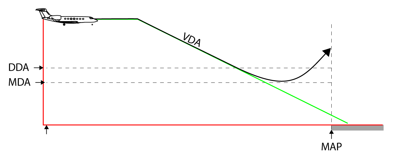
CDFA to DDA (my drawing)
An increment for the MDA/H may be prescribed by the operator to determine the altitude/height at which the vertical portion of the missed approach shall be initiated in order to prevent descent below the MDA/H. In such cases, there is no need to increase the RVR or visibility requirements for the approach. The RR and/or visibility published for the original MDA/H should be used.
Source: ICAO Doc 8168, Vol I, ¶ 1.8.2.4
While some countries specify the method used to determine the DDA, most do not. In the case of the Gulfstreams that I have flown, the manufacturer measures the maximum altitude loss during a coupled go around and prescribes that as the increment to be added to the MDA to determine the DDA. In the GVII, for example, the increment is 50 feet.
9
Flying a CDFA
Before the approach
Before starting the approach, pilots must study the procedure to ensure it is appropriate for a CDFA. Circling approaches are rarely suitable, and neither are approaches with obstacles close-in to the runway or those with high descent rates required.
Pilots should brief aircraft unique procedures needed to establish the proper vertical descent, to track the descent’s progress, to announce the DDA, what to expect if landing from the CDFA, and what to do if a missed approach is needed at the DDA.
Leaving the FAF
The objective of the CDFA is to leave the final approach fix fully configured, on speed, and ready to land. You should not have to destabilize the aircraft by making airspeed or trim adjustments when spotting the runway. GV and G550 pilots often withhold the last increment of flaps as a courtesy to faster moving aircraft, but if flying a CDFA in instrument conditions, it may be wiser to configure earlier.
This technique requires a continuous descent, flown either with VNAV guidance calculated by on-board equipment or based on manual calculation of the required rate of descent, without level-offs. The rate of descent is selected and adjusted to achieve a continuous descent to a point approximately 15m (50 ft) above the landing runway threshold or the point where the flare manoeuvre should begin for the type aircraft flown. The descent shall be calculated and flown to pass at or above the minimum altitude at any step-down fix.
Source: ICAO Doc 8168, Vol I, ¶ 1.8.2.2
Some aircraft allow a CDFA be flown with ILS-like indications so that procedures can be identical. Others may require adjustments, such as lowering the altitude select to field elevation. The closer CDFA procedures can be to an ILS, the better. Pilots simply follow the needles down to minimums, being mindful of the DDA. (Pilots should consult their aircraft manuals and practice these procedures in a simulator until comfortable.)
In a relatively “low tech” airplane that doesn’t give you an autopilot or flight director coupled angle to fly, pilots should convert the VDA to a descent gradient and set that as an initial descent rate.
Tracking progress
Highest Tech. If you are using a Head Up Display (HUD) you should be able to monitor a Flight Path Vector (FPV) symbol’s position over the runway and later fine-tuned to over the touchdown zone. See: Head Up Display Techniques.
High Tech. If your FMS provides a distance countdown to the end of the runway, you should be able to check that against altitude to see if you are above or below your continuous descent angle. You can estimate the correct distances by multiplying the distance in nautical miles by 318 feet and then adding 50’ for the threshold crossing height. (Since the CDFA is aimed to the touchdown zone, you altitude will need to be 50’ higher at each marker. You can do the math or use the chart below.
Low Tech. You can check your progress during the approach by placing tick marks on your approach plate at each mile from the final approach fix to the missed approach point with the appropriate altitude. Once again you can do the math as shown under the “High Tech” example, or use the chart below.
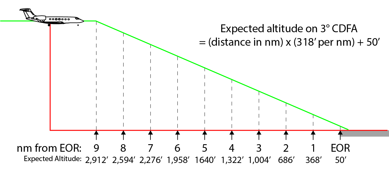
Altitude versus distance (my drawing)
Going missed approach
The CDFA places the aircraft right on glide path in a position to land in the touchdown zone of the runway. If the runway is sighted after this point, the aircraft will be too far down the runway to make that happen and a missed approach will be needed. This eliminates the judgment calls when sighting the runway early or late.
If the visual references required to land have not been acquired when the aircraft is approaching the MDA/H, the vertical (climbing) portion of the missed approach is initiated at an altitude above the MDA/H sufficient to prevent the aircraft from descending through the MDA/H. At no time is the aircraft flown in level flight at or near the MDA/H. Any turns on the missed approach shall not begin until the aircraft reaches the MAPt. Likewise, if the aircraft reaches the MAPt before descending to near the MDA/H, the missed approach shall be initiated at the MAPt.
It should be emphasized that upon reaching the MDA/H only two options exist for the crew: continue the descent below MDA/H to land with the required visual references in sight; or, execute a missed approach. There is no level flight segment after reaching the MDA/H.
Source: ICAO Doc 8168, Vol I, Part I, Amdt 3, ¶1.7.2.3 and ¶1.7.2.6
This technique causes you to execute the missed approach prior to the actual missed approach point. Therefore, the standard procedure for this situation applies: immediately climb but delay any turns until the MAP.
Executing a Missed Approach Prior to MAP. When executing a missed approach prior to the MAP and not cleared for an air traffic control (ATC) climbout instruction, fly the published missed approach procedure. Proceed on track to the MAP before accomplishing a turn.
Source: AC 120-108A, §3.7 to 3.9
References
(Source material)
Advisory Circular 120-108A, Continuous Descent Final Approach, 3/22/23, U.S. Department of Transportation
FAA-H-8083-15B, Instrument Flying Handbook, U.S. Department of Transportation, Flight Standards Service, 2012
FAA-H-8083-16B, Instrument Procedures Handbook, U.S. Department of Transportation, Flight Standards Branch, 2017
EASA Air Ops Annex 1 to VIII, European Aviation Safety Agency, October 2019
ICAO Doc 8168 - Aircraft Operations - Vol I - Flight Procedures, Procedures for Air Navigation Services, International Civil Aviation Organization, Sixth Edition, 2018