What I don't know about Airbus flight control laws would fill an entire page. This page, to be specific.
— James Albright

Updated:
2015-04-30
The only reason I try to understand this is to get a better understanding of the Airbus mishaps that interest me:
- Airbus A320-232 D-AXLA (FCF)
- Air Blue 202 (CRM, Circling Approach, CFIT, Situational Awareness)
- Air France 296 (Fault Tolerance, Complacency)
- Air France 447 (Situational Awareness)
- Air Transat 236 (Fuel Leak, Situational Awareness, Systems Knowledge)
- United Parcel Service (UPS) 1354 (CFIT, fatigue, continuous descent final approach, callouts, stabilized approach)

1
General concepts
The Airbus flight control surfaces are moved by commands from several flight control computers in response to pilot input. This system is referred to as "fly-by-wire" as there is no mechanical connection between the sidestick and the control surfaces. The relationship between sidestick input and the aircraft response is called the flight control law. Depending upon the status of the fly-by-wire system, three sets of control laws are provided, i.e. Normal Law, Alternate Law and Direct Law. In the unlikely event of a failure causing a complete loss of the fly-by-wire system, the aircraft can be flown safely through a backup system while the crew complete actions to recover one of the control laws.
Source: Airbus FTCM, pg. 2.60.1
2
Normal law
Under most circumstances, the aircraft is operated in Normal law. Normal law is designed to accommodate single system failures and has three modes:
- Ground Mode
- Flight Mode
- Flare Mode
The transition from one mode to the next is transparent to the pilot.
Source: Airbus FTCM, pg. 2.60.1
Ground Mode
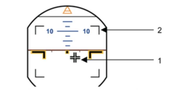
Normal law, ground mode display, from Airbus FTCM, pg. 2.60.1.
On the ground and at low speeds, the sidesticks have full authority over the controls in pitch and roll. Ground mode is progressively blended out after take-off as the flight mode becomes active.
When the aircraft is on the ground, the PFD includes a symbol (1) that is the sum of the sidestick positions given to the flight control computers. It permits the PNF to check that the PF is making the appropriate control input during the take-off roll.
Small limit marks (2) indicate the limits of stick travel (±16° in pitch, ±20° in roll).
Do not use this display for flight control checks because it does not indicate flight control position.
Source: Airbus FTCM, pg. 2.60.1
Flight Mode
Normal law, ground mode display, from Airbus FTCM, pg. 2.60.1.
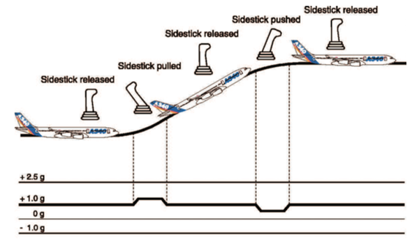
In pitch, when an input is made on the sidestick, the flight control computers interpret this input as a “g” demand/pitch rate. Consequently, elevator deflection is not directly related to sidestick input. The aircraft responds to a sidestick order with a pitch rate at low speed and a flight path rate or “g” at high speed. When no input is made on the sidestick, the computers maintain a 1g flight path. Pitch changes due to changes in speed, thrust and/or configuration, which in a conventional aircraft would require the pilot to re-trim the aircraft, are compensated for by the computers repositioning the THS. The pitch trim wheel moves as the control law compensates for these changes. Sometimes, changes of trim due to changes in thrust may be too large for the system to compensate, and the aircraft may respond to them in pitch in the conventional sense and then hold the new attitude at which it has stabilised after the trim change.
Due to its neutral static stability, the aircraft maintains the selected flight path. Should it deviate however, only small sidestick inputs are required to regain the desired flight path.
Source: Airbus FTCM, pg. 2.60.2
Normal law, normal speed envelope, from Airbus FTCM, pg. 2.60.3.
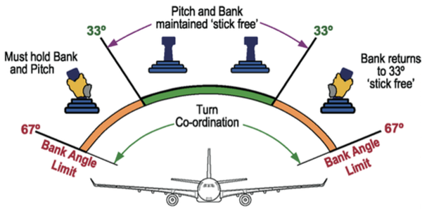
In roll, when an input is made on the sidestick, the flight control computers interpret this input as a roll rate demand. Consequently, aileron and/or spoiler deflection is not directly related to sidestick input. When no input is made on the sidestick, the computers maintain a zero roll rate. At bank angles less than 33° with no input being made on the sidestick, the computers maintain a zero roll rate and, consequently, the aircraft will maintain a constant bank angle. Within this range, there is no need to make a correction in pitch, as this will be compensated for by the computers. Beyond 33° angle of bank, pitch compensation is no longer available. On releasing the sidestick to neutral, the aircraft rolls back to 33° angle of bank.
Due to its neutral static stability, within 33° angle of bank, the aircraft maintains the selected flight path. Should it deviate however, only small inputs are required on the sidestick to regain the desired flight path. The control law provides turn co-ordination, so there is no need to use the rudder.
As the flight mode is always aiming to achieve the selected flight path, avoid the temptation to over-control. The recommended method to avoid over-controlling is to make a small sidestick input, hold for a short period and then return the sidestick to neutral. Even in turbulent conditions, the control law resists the disturbances well without pilot inputs. The pilot should try to limit his control inputs to that necessary to correct the flight path trajectory and leave the task of countering air disturbances to the flight control system. If the pilot senses an over-control, the sidestick should be released.
In climb, cruise, descent and approach, all these basic rules remain in effect.
Source: Airbus FTCM, pg. 2.60.3
Flare Mode
To perform the flare and landing, the flight controls need to be responsive and linear. Therefore on reaching 100 ft on the approach the pitch law is modified to be a full authority direct law with no auto-trim. A nose down term is introduced which requires the pilot to maintain a backpressure on the sidestick to achieve a progressive flare, as in a conventional aircraft. After touchdown, the control law progressively reverts to ground mode.
Source: Airbus FTCM, pg. 2.60.4
3
Protections
Normal Law provides five different protections:
- High Angle of Attack Protection
- Load Factor Protection
- High Pitch Attitude Protection
- High Speed Protection
- Bank Angle Protection
The protections are complementary and together work to maintain the aircraft in the safe flight envelope. If an extreme manoeuvre is required, the pilot can make full sidestick inputs in normal law at any speed. This normal law protection does not apply to the rudder as it is not normally used in symmetrical flight.
However, it is important to remember that the normal flight envelope is defined as VLS to VMO/MMO. Pilots should not deliberately fly at a speed outside of the normal envelope unless absolutely necessary for operational reasons.
Source: Airbus FTCM, pg. 2.60.4
High Angle of Attack Protection
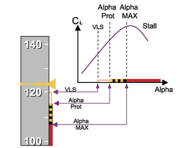
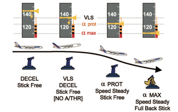
High angle of attack protection airspeed tape indications, from Airbus FTCM, pg. 2.60.4.
The high angle of attack (AOA) protection allows the pilot to consistently achieve the best lift while preventing the aircraft from stalling.
The following description illustrates a sequence of events that would lead to the activation of the various stages of high AOA protection.
In level flight, if the A/THR is disengaged and thrust set to idle, the aircraft decelerates until the auto-trim stops. This occurs at a predetermined angle of attack called Alpha Prot. The speed that equates to Alpha Prot (Va PROT) is displayed as the top of a black and amber strip on the PFD speed scale. If no input is made on the sidestick, the aircraft will descend to maintain its current AOA (Va PROT). To maintain the flight path, the pilot must increase the backpressure on the sidestick, which also provides a tactile indication that auto-trim has stopped. At Va PROT, AOA protection becomes active and, if the sidestick is released to neutral and no thrust applied, the aircraft will gently descend maintaining Va PROT. When AOA protection is active, the speed brakes retract automatically, if previously extended, and the bank angle limit is reduced from 67° to 45°.
If the pilot maintains the backpressure, Alpha Floor (covered below) will activate. If the pilot disconnects the A/THR while maintaining full back stick, Alpha Max may be reached. The speed which equates to Alpha Max (Va MAX) is displayed as the top of the red strip on the PFD speed scale. Alpha Max is close to, but short of the 1g stall. When flying at Va MAX, the pilot can make gentle turns if necessary. In turbulence, airspeed may fall temporarily below Va MAX without significant effect.
Source: Airbus FTCM, pg. 2.60.4
Airspeed tape indications (deceleration with no a/thr), from Airbus FTCM, pg. 2.60.6.
These features are aerodynamic protections. Additionally, there are three energy features that enhance these protections:
- With the A/THR engaged, the aircraft will not decelerate below VLS (displayed as top of amber strip) even if the target speed is selected below VLS.
- A low energy aural warning is triggered when the aircraft energy level is below a given threshold. This energy level is a function of several parameters including aircraft configuration, speed, horizontal deceleration rate, flight path angle and altitude. (FCOM 1.27.20 refers) The aural warning "SPEED, SPEED, SPEED" alerts the pilot of the requirement to adjust thrust and flight path. It is triggered during deceleration before Alpha Floor (unless Alpha Floor is triggered by stick deflection). The delay between the aural warning and Alpha Floor activation is a function of deceleration rate.
- If Alpha Prot is reached and the pilot still maintains aft sidestick, Alpha Floor protection (set between Alpha Prot and Alpha Max) will be reached. This protection triggers the application of TOGA thrust and the aircraft will start to climb at a relatively constant low airspeed. Alpha floor protection is inhibited in some cases.
The aircraft can also enter alpha protection at high altitude, where it protects the aircraft from the buffet boundary. The PFD shows that alpha protection is active in the same way as at low speed and low level: the amber and black strip rises to the actual speed of the aircraft. As at low speed and low level, if the stick is merely released to neutral the aircraft maintains the alpha for alpha protection.
Source: Airbus FTCM, pg. 2.60.6
Load Factor Protection
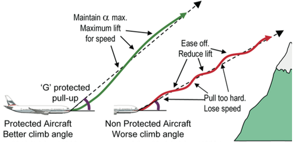
Protected/non-protected aircraft climb angle comparison, from Airbus FTCM, pg. 2.60.7.
On most commercial aircraft, the maximum load factor range is 2.5g/-1g clean and 2g/0g with slats and/or flaps extended. The load factor protection is designed to maintain the aircraft within these limits while allowing the crew to consistently achieve the best achievable aircraft performance, if required.
On commercial aircraft, high load factors are most likely to be encountered when the pilot responds to a GPWS warning. Airline pilots are not accustomed to using "g" as a flying parameter and experience has shown that, in emergency situations, the application of "g" is initially hesitant and then aggressive. If a GPWS alert is generated which requires an immediate pull-up, full back stick should be applied and maintained. The load factor protection will allow maximum "g" to be achieved in the shortest time while preventing the aircraft from being overstressed.
Source: Airbus FTCM, pg. 2.60.7
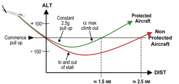
CFIT escape manoeuvres on protected and non-protected aircraft, from Airbus FTCM, pg. 2.60.8.
If the pilot maintains full aft stick because the danger still exists, the high AOA protection will eventually take over. This is one instance where load factor protection is enhanced by the high angle of attack protection.
Source: Airbus FTCM, pg. 2.60.8
High Pitch Attitude Protection
Excessive pitch attitudes, caused by upsets or inappropriate manoeuvres, lead to hazardous situations. Even the most extreme emergency situations do not require flying at excessive pitch attitude. For this reason, high pitch attitude protection has been designed to be part of the flight control system. The high pitch attitude protection limits the pitch attitude to +30°/-15°. The 30° limit decreases to 25° at low speed. If the aircraft approaches these limits, the pitch and roll rates start to decrease 5° before the limit so that it will stop at the limit without overshooting.
Source: Airbus FTCM, pg. 2.60.8
High Speed Protection
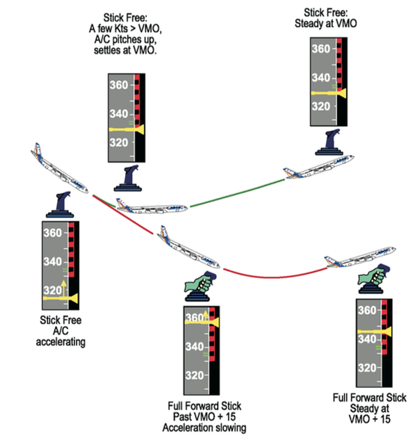
CFIT escape manoeuvres on protected and non-protected aircraft, from Airbus FTCM, pg. 2.60.9.
Beyond the maximum design speed of the aircraft, VD/MD (which is greater than VMO/MMO), there are potential aircraft control problems due to high air loads. Therefore the margin between VD/MD and VMO/MMO must be such that any possible overshoot of the normal flight envelope does not cause controllability problems.
In order to protect the aircraft from dangerous phenomena at high speed, a positive nose up "g" demand up to 1.75g is added to the pilot demand on the sidestick when exceeding VMO/MMO. Additionally, if the side stick remains forward, the sidestick nose down pitch authority is smoothly reduced to zero at approximately VMO + 16/MMO + 0.04. With reference to the diagram below, if a dive is achieved with stick free, the aircraft will slightly overshoot VMO/MMO and fly back into the flight envelope. If a dive is achieved with the sidestick fully forward, the aircraft will significantly overshoot VMO/MMO but without reaching design speed limits, VD/MD
When high speed protection is triggered, the autopilot disconnects, the pitch trim is frozen, the spiral static stability is reduced from 33° to 0° of bank and the limit bank angle is reduced from 67° to 45°. If high speed protection is active with the aircraft established in a turn, when the sidestick is released the aircraft will roll wings level. This increased spiral stability reduces the risk of a spiral dive.
Source: Airbus FTCM, pg. 2.60.8
Bank Angle Protection
On commercial aircraft, 30° bank angle is normally not to be exceeded. A bank angle of 67° in level flight corresponds to the aircraft limit of 2.5 g. Therefore, 67° has been established as the bank angle limit. Approaching this limit, the roll rate is progressively reduced to avoid over-banking.
This 67° bank angle limit is reduced to 45° in case of high speed protection.
Source: Airbus FTCM, pg. 2.60.10
4
Alternate law
In some cases of double failure, e.g. double hydraulic failure, the integrity and redundancy of the computers and other required systems are not sufficient to achieve normal law with its protections. In this case, Alternate Law is triggered. VLS remains, but á prot and á max disappear, replaced by a single black and red strip, the top of which is the stall warning speed VSW. Unlike VLS which is stable, VSW is g sensitive so as to indicate margin above stall during turns. The autopilot may be available depending on the cause and type of failure(s). During landing, alternate law reverts to direct law at 100 ft RA.
If the aircraft is operated outside the normal flight envelope, the pilot must take appropriate corrective action to avoid losing control and/or to avoid high speed excursions, since the normal law protection features may not be available.
Handling Characteristics
In pitch, handling remains similar to normal law.
In roll, depending on the failure level, control is either normal (ALTN 1) or direct (ALTN 2). In roll direct, the aircraft appears to be very sensitive and bank stability is no longer active.
Source: Airbus FTCM, pg. 2.60.10
Protections
In Alternate Law the protections change as follows:
- High angle of attack protections are replaced by stall warning at 1.03 VS1g
- The load factor protection is maintained
- The pitch attitude protection is lost
- The high speed protection is replaced by overspeed warning
- The bank angle protection is maintained if roll is normal (ALTN 1) but lost in roll direct (ALTN 2)
Source: Airbus FTCM, pg. 2.60.10
5
Direct law
In most cases of triple failure, e.g. triple ADR failure, direct law is triggered. Autopilot and auto-trim are not available.
Source: Airbus FTCM, pg. 2.60.11
Handling Characteristics
The handling characteristics are similar to a conventional aircraft. Any tendency to roll stick free can be corrected by conventional use of the rudder. Rudder trim can be used in the conventional way, but note that the sideslip index may be slightly displaced from the centre once the rudder forces have been trimmed out. Rapid speedbrake application and large thrust changes will result in significant pitching moments, i.e. nose-up with thrust increase and nose down with thrust reduction.
In pitch, elevator deflection is proportional to sidestick deflection. It is important to note that the controls are very powerful. Consequently, use small inputs when at high speed. As there is no auto-trim, use manual trim making small inputs on the trim wheel.
In roll, aileron and spoiler deflection is proportional to sidestick deflection. Direct law works with the yaw damper to provide a minimal turn coordination.
Source: Airbus FTCM, pg. 2.60.11
Protections
No protections are available but overspeed and stall aural warnings remain available.
Source: Airbus FTCM, pg. 2.60.11
6
Backup system
The purpose of the backup system is to allow control of the aircraft following a total loss of electrics, flight control computers, elevators, or ailerons and spoilers. It is designed to allow the crew to safely stabilise the flight path while attempting to recover a control law or restore a lost system(s). It is not intended that an approach and landing should be flown in this configuration.
Source: Airbus FTCM, pg. 2.60.11
Handling Characteristics
Stabilise the aircraft flight path using the rudder and manual pitch trim while attempting to recover a flight control law. Thrust considerations regarding pitching moments are similar to those described above in Direct Law.
Pitch control is achieved through the pitch trim wheel. Make small inputs on the trim wheel and wait for the aircraft response before making a further correction.
Lateral control is achieved through the rudder. The rudder induces a significant roll with a slight delay. Make small inputs on the rudder pedals and wait for the aircraft response before making a further correction. Wings level stabilisation needs some anticipation.
Source: Airbus FTCM, pg. 2.60.11
7
Abnormal attitude law
If the aircraft is far outside the normal flight envelope and reaches some abnormal attitudes, the flight control law is modified to allow the crew to regain normal attitude efficiently. This is the abnormal attitude law.
Source: Airbus FTCM, pg. 2.60.12
References
(Source material)
Airbus A330/340 Flight Crew Training Manual, Rev 1, 6 Jun 05